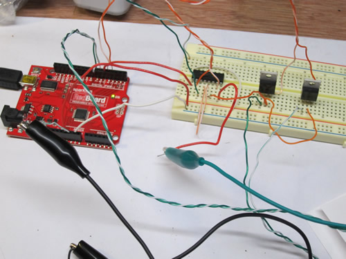

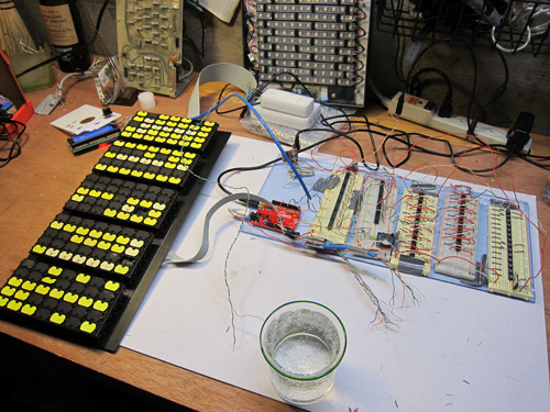
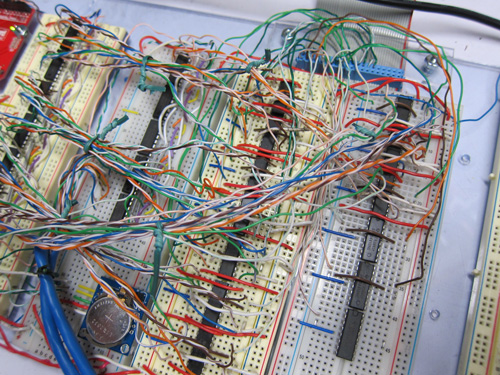
Despite these problems, the circuit is beginning to take shape. From the far left:
Arduino Uno
Shift registers to ultimately control 25 columns
H-Bridges to handle the reversing of polarity that's needed to flip both directions
A couple more shift registers to handle the 14 rows (7 x 2) and the transistors to power each row
I tend to work on multiple things in parallel (keeps the frustration level down).
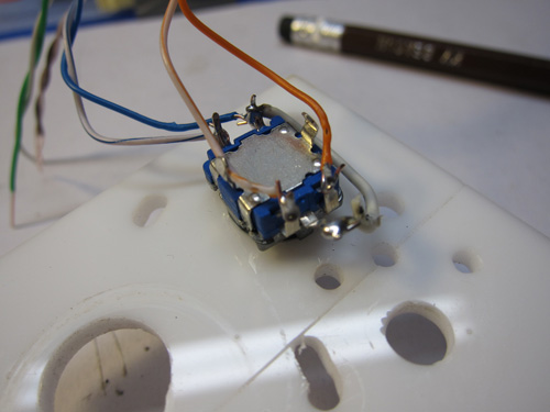
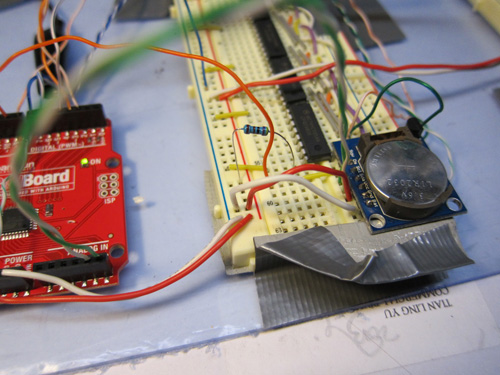
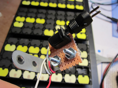
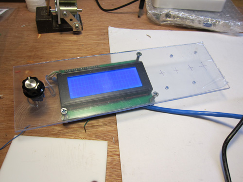
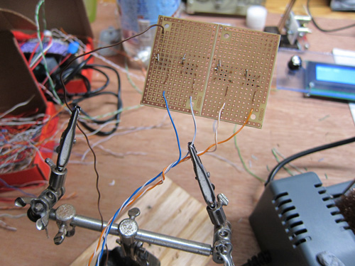
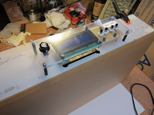
This is the rotary encoder, which is part of the control panel. It also has a "push to set" capability, which means the end user can rotate the dial until the correct menu item shows up on an LCD, then push it to enable/disable the feature.
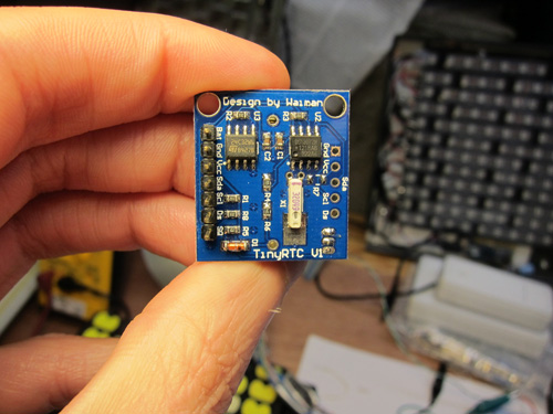
I mounted the RTC next to the shift registers. The clock runs on the I2C serial protocol, so just needs a data and clock wire to communicate to the Arduino.
The temperature sensor is a separate, one-wire protocol.
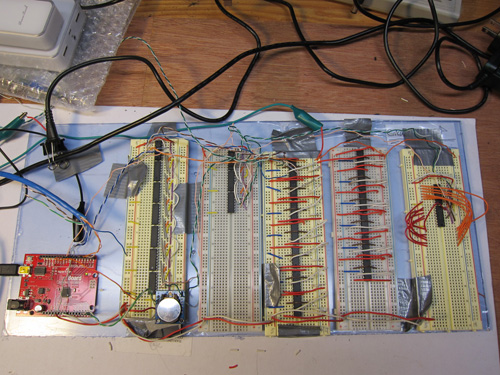
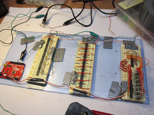
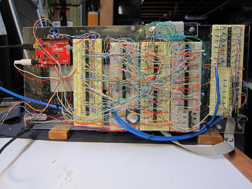
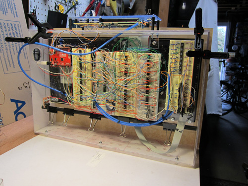
From early on I wanted the clock to be as transparent as possible; that's why the breadboards are mounted on a sheet of clear acrylic, which I cut to be the same size as the Flip Dot display (it would also force me to keep the circuit small, and iterate in order to find the most efficient placement of components!)
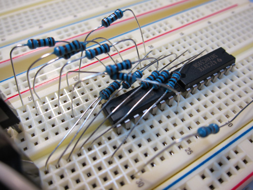
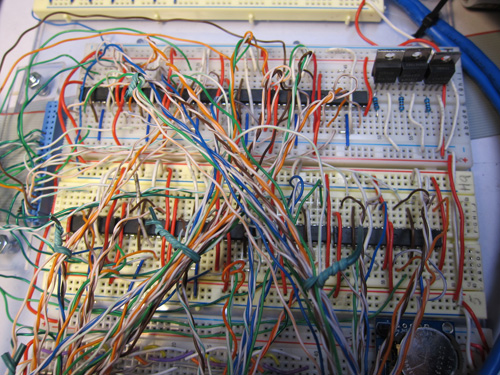
Here, I've added more shift registers and H-Bridges. On the far right, you'll see I've removed the transistors. My solution to control each row wasn't working.
Hardware is hard - that's why it's called hardware. Everything needs to be designed, and the power connector is no different. Ultimately, this gets mounted on the acrylic sheet.
Bonus points if you spotted the token bit of Meccano!
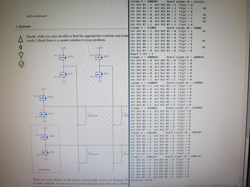
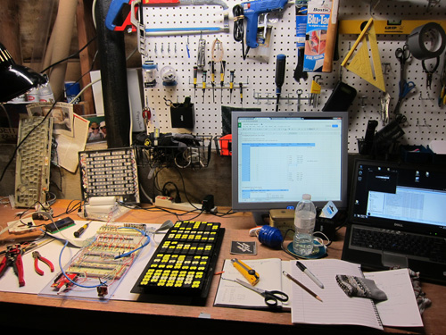
On the right, you can see a debug trace from when I was writing the code to magically convert a number into the 1's and 0's necessary to flip the dots the right way. I'm quite proud at the code I wrote; very efficient.
In the background is an electronics.stackexchange.com response to my ever-more desparate cries for help to get the dots to flip consistently.
After more research on the row-control problem, I tried using TIP-120 transistors (the bottom seven) to control the dots flipping from black to yellow. And a clever little digital relay, called an LCA710, to flip dots the other way.
This had an immediate impact on reliability and consistency of flipping, although it was by no means perfect. But it led me to believe I'm at least on the right track.
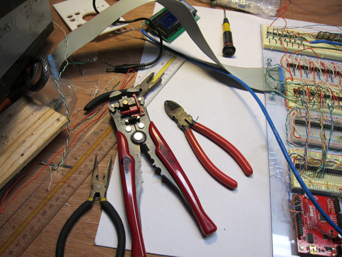
Tools of the trade. Because I cut all my own wires from a bulk Ethernet reel (thanks, Jameco.com!) the wire stripper has been used thousands of times, and saves hundreds of hours.
If you're wondering why I'm stripping wires and using breadboards, instead of fabbing PCBs, it's because this is a one-off project and I need the flexibility to tweak and experiment with the circuit. There is no "master plan!"
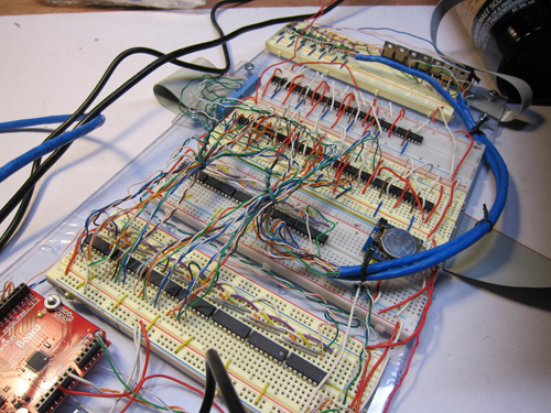
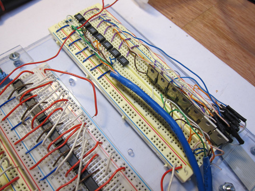
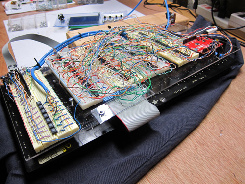
You can begin to see the jungle of wires that are growing as I connect shift registers to H-bridges.
Each H-bridge can control two columns. Each column needs three inputs (to turn it on or off, and to specify the polarity), so three pins of a shift register are needed for each column. That's 3 wires per column x 25 columns = 75 strands of wire.
That's no counting all the wires to daisy chain the shift registers together, nor to provide power to the H-bridges and, of course!, to send the power to the board. Lots and lots of wires.

These black buttons (actually spacers) are glued onto a white piece of plastic. Then the button touches the microswitch, underneath. This solution is very reliable.
The buttons will control time adjustment, turn the chime on or off, and put the clock in sleep/wake mode.
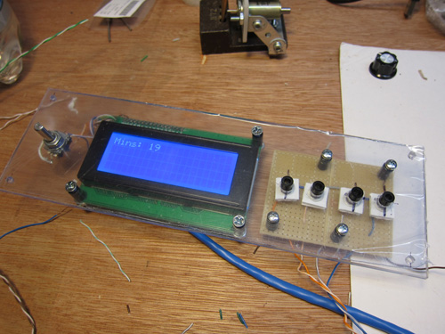
Here I've got everything on the control panel wired up. The blue Ethernet cable carries all the wires for the LCD display and rotary encoder. The other straggling wires are for the four pushbuttons. I like the look of this control panel - and how you can see inside, without it looking too messy.
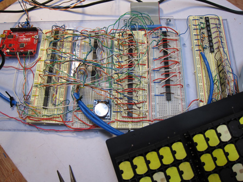
The circuit now has almost all the components on it - shift registers, H-bridges and transistors/relays. Likewise, the wires are multiplying! I went column-by-column, making sure every row on each column worked before proceeding to the next. I did that because of numerous problems - wires that weren't properly settled in the breadboard, routing errors on my part, and other occasional issues that I hadn't yet solved (related to the inconsistent ability to flip certain rows). Still, we're getting close.
By this point, I've wired up 20 of the 25 columns, and have written some code to draw a horizontal line. Like with all software, once you have control over one part of a system, the rest can be abstracted and you can be confident you can control the rest.
Man, that's a lot of wiring. And I've still got three H-bridges to go.
At the top of the picture, you can see a female header (the blue thing). By debugging the flip dot display I was able to figure out which of those connections correspond to which columns. Those, in turn, are wired to each H-bridge.
All the H-bridges are wired up to the shift registers. I'm thinking once this circuit is proven, I'll hot glue all those wires in place. Even though I make copious notes when building projects, it's going to be a real pain to figure out where some random orange wire needs to go to if it's poking out.
The three TIP-120 transistors (top right) were for the first iteration of the clock chime.
I have a bunch of antique clocks in the house, and I love the chiming. Some clocks do quarter past, half past, quarter to, and at the top of the hour. My house often puts visitors to sleep with all the ticking, tocking and gentle chimes. So I thought this clock should be no different! I bought the chime rods on eBay, and created a chiming mechanism made from three solenoids. Unfortunately, the biggest bong was heard as the solenoid power was released, and the hammer fell down and him the chime. That means I also needed to have a motorized baffle to hold the hammers away from the chime when it wasn't in use. Plus, this was all getting rather big and complicated, and it didn't look like it would fit in the case I was building. I later re-imagined the chime.
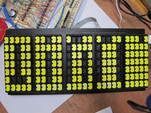
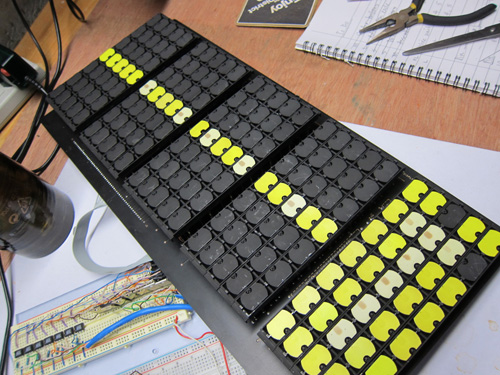
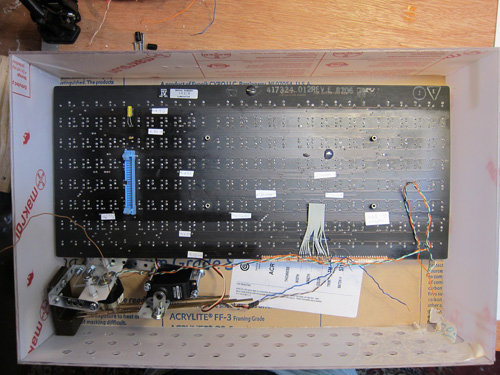
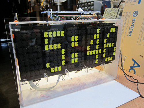
My flip dot display had clearly spent many serviceable years in a bus, and it showed - lots of dots were faded out. So I took out those, and replaced them with bright yellow dots (I bought several boards so had the luxury of doing this).
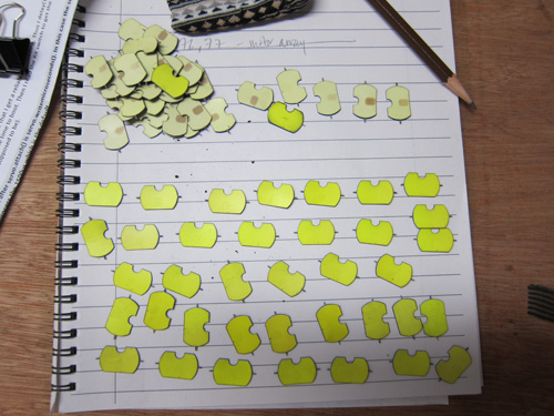
Faded dots on top, shiny replacements below.
Here's a test mount of the circuit board fastened to the back of the flip dot display (which is face down). The flip dot board had some mounting holes from its original enclosure, and I had drilled holes in the transparent acrylic at the beginning of this project. That's called planning ahead!
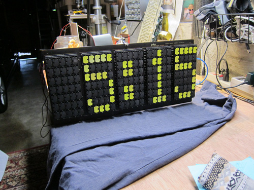
Wow, this is really starting to look like a clock!
The software is done for all the basic things, like rendering a character, but it's still missing more advanced features like sleep/wake times, chiming, showing cute pixel-based animations, and other stuff to fill up the Arduino's massive 32 Kb of memory.
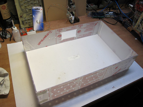
Starting to work on the enclosure. I went to TAP Plastics and board several sheets of scrap acrylic. Even that wasn't cheap; it was about $50, making it the single most expensive item in the project (even more than the flip dot board!).
I cut the plastic using a scroll saw (then I dirtied the ends with a Dremel in advance of cementing) and assembled the pieces together just to make sure everything would fit (the chime didn't, and that's part of the reason why I rebuilt it).
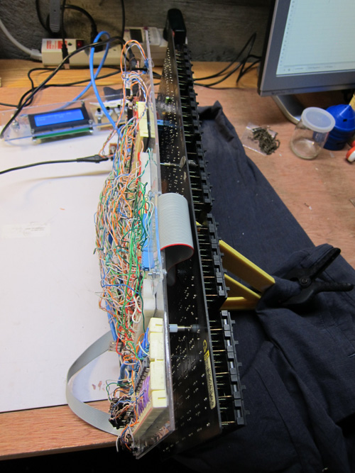
View from the top. It's about 5 inches deep, which was what I was aiming for. I didn't want something that was too bulky in the back.
View from the back. Ugh, that's a lot of wiring to go wrong and fall out over the years. Anyone want to build me a printed circuit board for this?
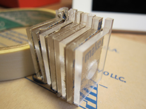
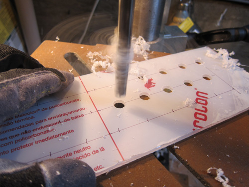
I cut out these plastic spacers to enforce a gap between the front of the flip dot board and the clear plastic face. That's because each dot needs about 12mm a space as it flips and rotates about its pivot point.
OK, time to glue this board permanently together. Measure twice, glue once!
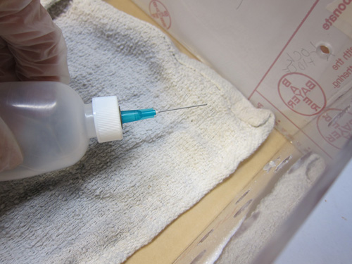
For acrylic, you use a special type of cement. It actually melts the area where two pieces of plastic meet, then solidifies again with seconds. It's more like welding. Needless to say, you do not want to get this chemical on your skin or in your eyes. Latex gloves and safety glasses at all times!
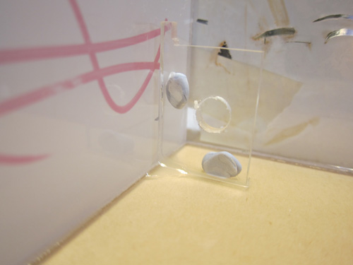
Here's one of those plastic spacers. I used Blu-Tack to hold them in place while I used the cement applicator, but that turned out to be not so good an idea… the cement gathered around the Blu-Tack and burned gashes into the acrylic. Luckily, they're tiny, and only I know where to look.
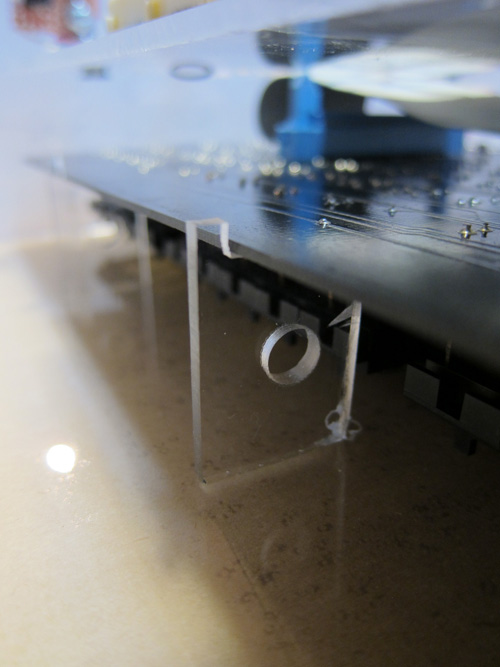
The flip dot board rests against the spacer, giving the dots enough clearance to flip.
Control panel mounted. Check!
By golly, everything seems to fit. I added that black bar near the bottom to provide some support for the flip dot board and circuit board.
Yeah, this is looking pretty nice.
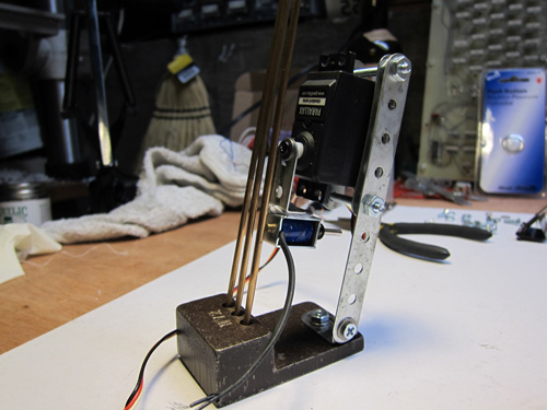
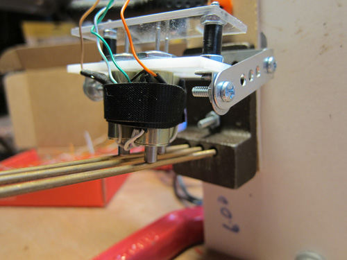
I re-engineered the chime to use a servo motor, which moves the solenoid into place. When the solenoid is energized it hits one of the three chime bars. This is a much more elegant solution than the one I had before, and uses fewer parts.
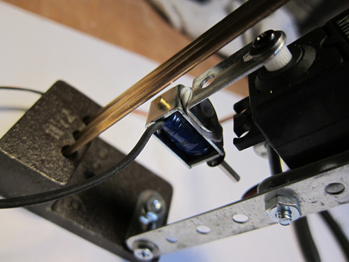
Yes, I did replace the Blu-Tack with hot glue.
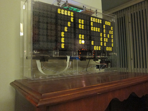
And that's it - a finished flip dot clock. I call her Dottie. If you haven't seen the video, scroll to the top of this page and check out Dottie's dulcet chimes and mesmerizing flipping. Then, you build one that's better!