 |
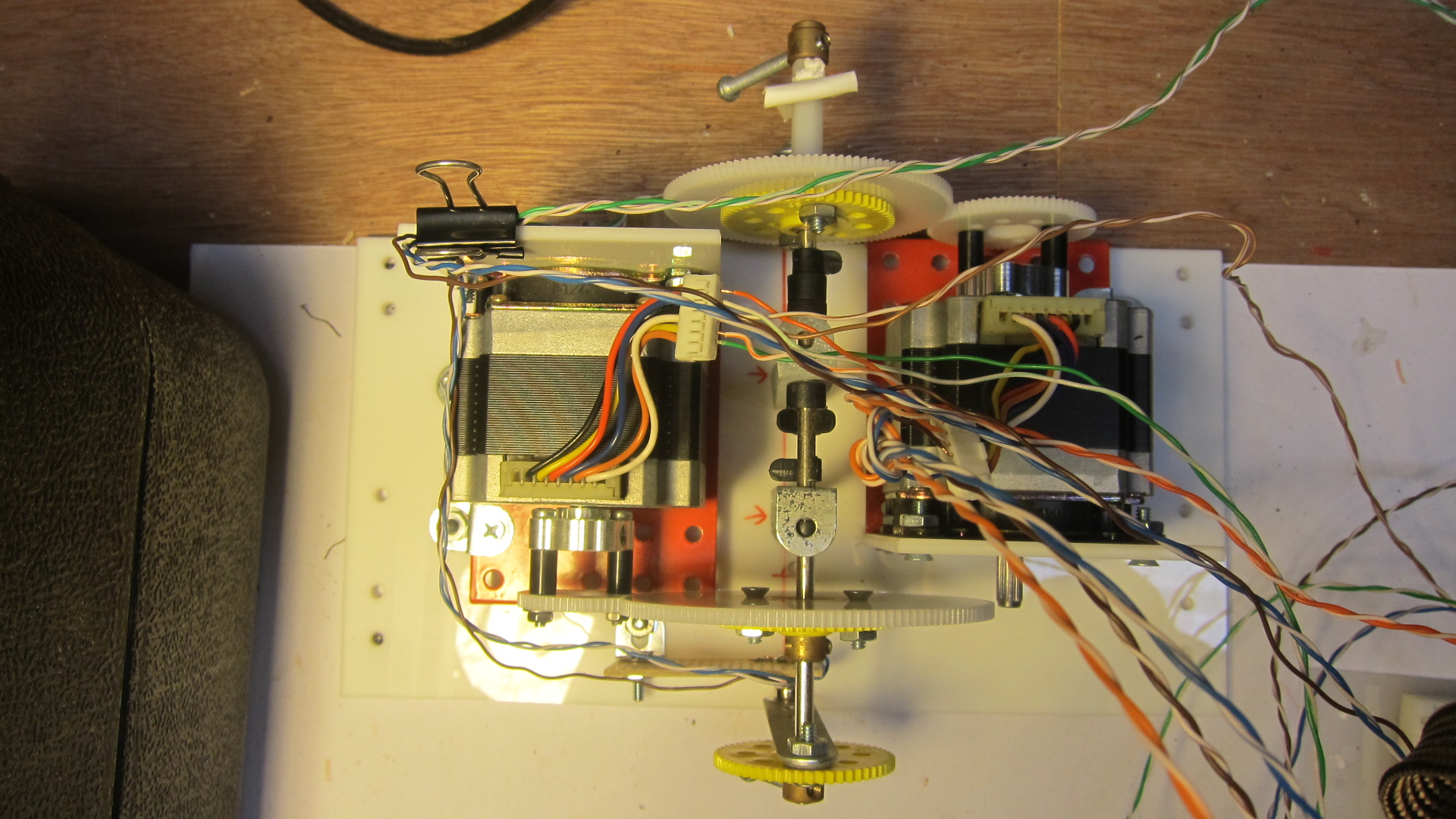
I started work on the movement. I'd built a clock a few years ago which used this threaded-axle design: from the rear, a motor turns a shaft that runs all the way to the front of a clock. This is the minute hand. In the front of the movement, another hollow shaft wraps around the inner one, and can turn independently. This is the hour hand.
|
 |
Being able to turn the hands a specific degree of rotation was important, so I use these stepper motors. If the minute hand has to move forward ever-so-slightly as time advances from 6 minutes 25 seconds to 6 minutes 27 seconds, the stepper motors provide for that kind of small adjustment.
|
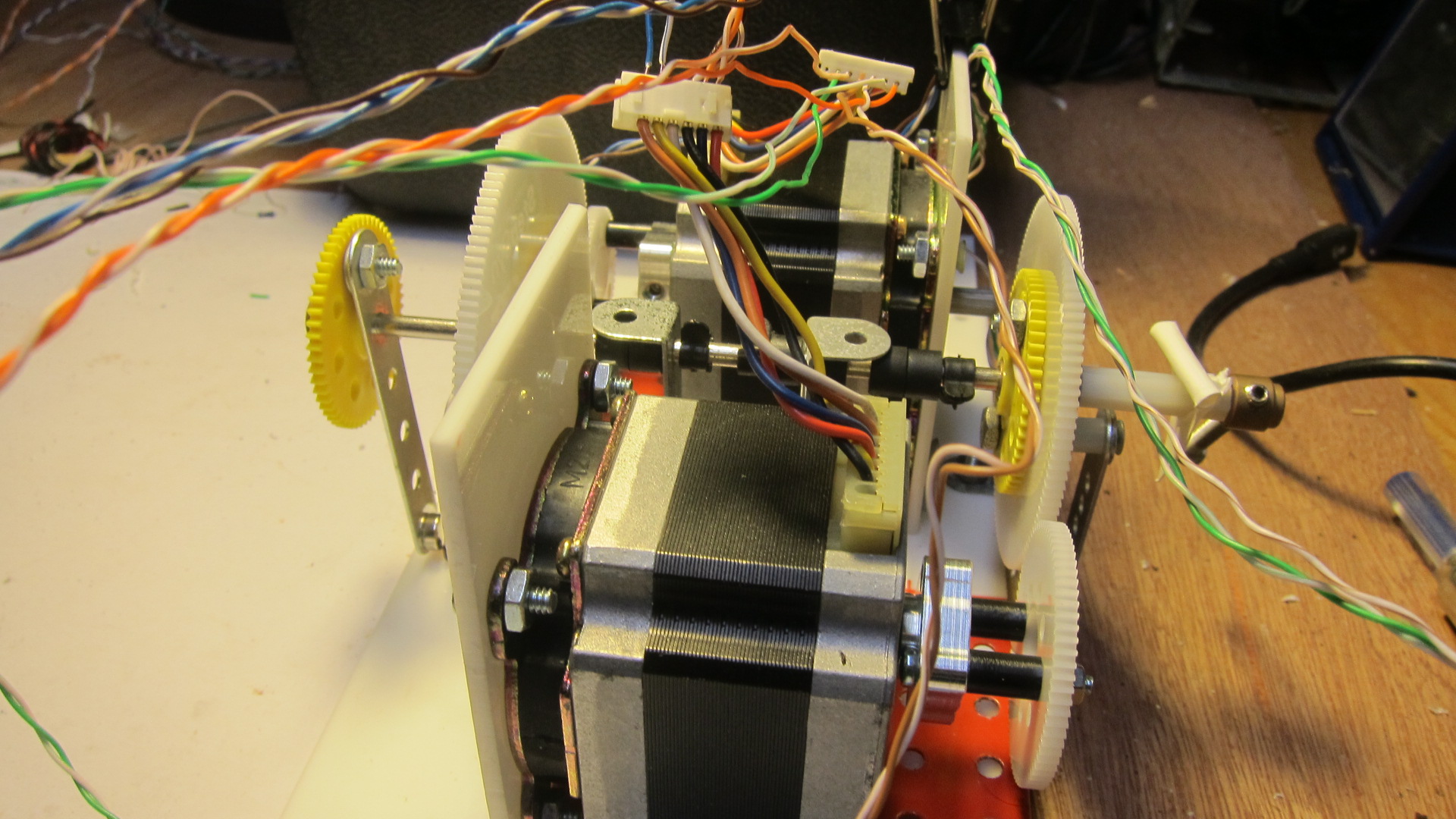 |
The first iteration of the movement worked, but it was quite bulky because of the size of the stepper motors (bought from eBay and taken from a photocopier, I think). I started searching Amazon for something smaller.
|
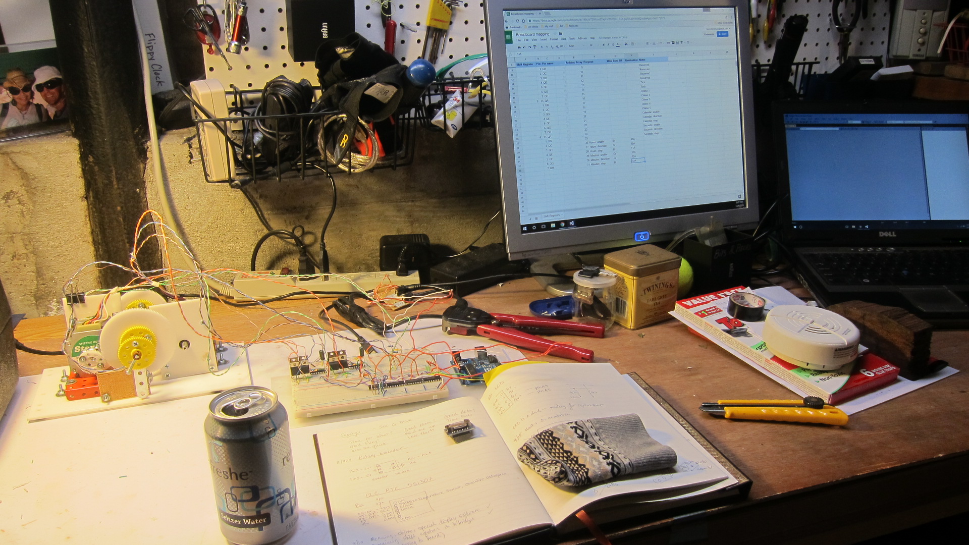 |
My workshop in my garage in San Francisco, California. I keep a paper notebook with my build notes; in Google Drive I keep a record of important circuit design notes; and I use Microsoft Visual Studio + the brilliant Visual Micro Arduino IDE for development.
|
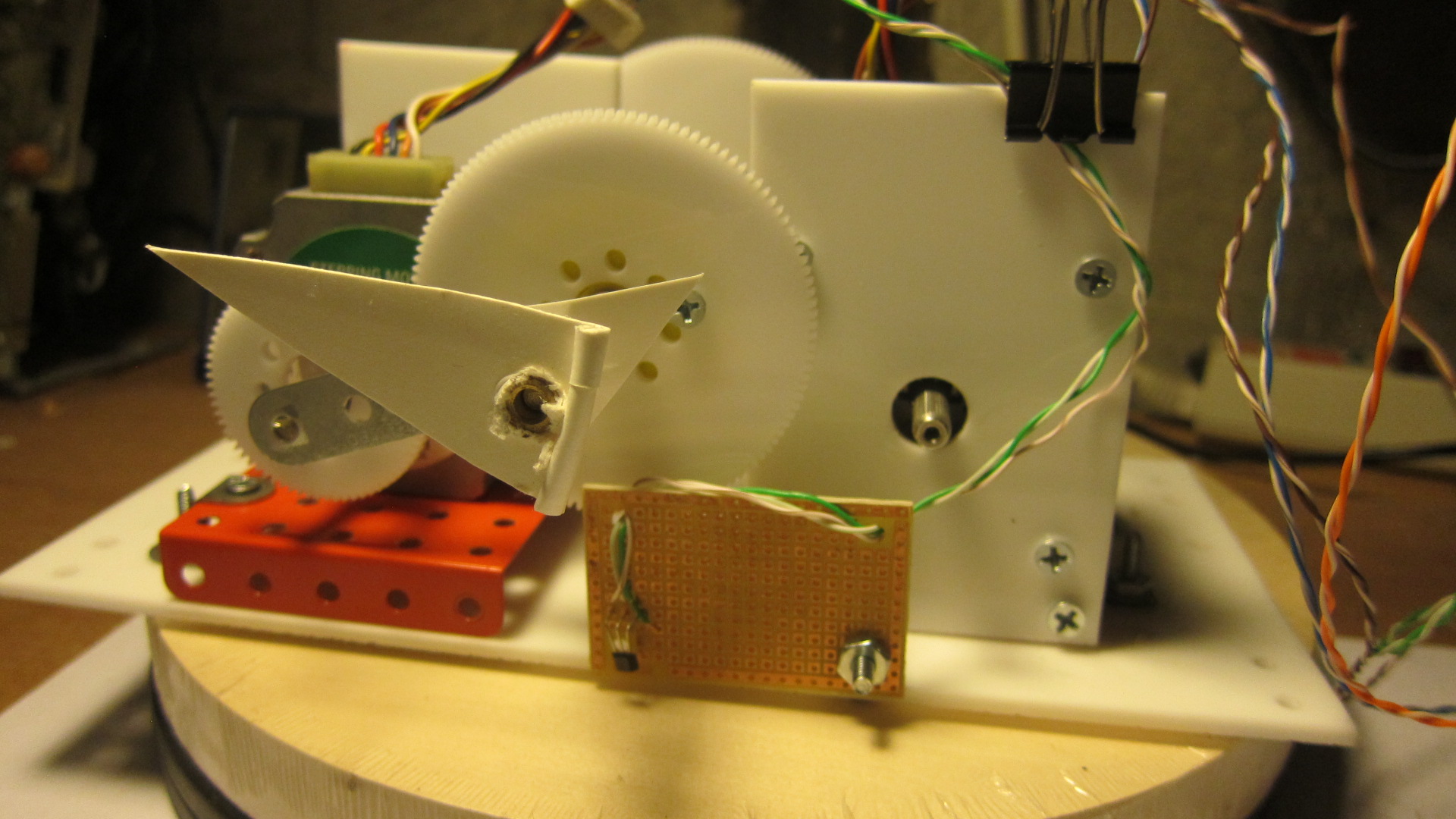 |
Front of the movement with paper hour and minute hand. The small brown board holds a hall-effect sensor. It senses when a magnet passes it (the magnet's attached to the metal bar) and sends a message back to the Arduino. That's how the program knows when each of the hands and dials are at the 12 o'clock position. That's essential for figuring out where each hand should point.
|
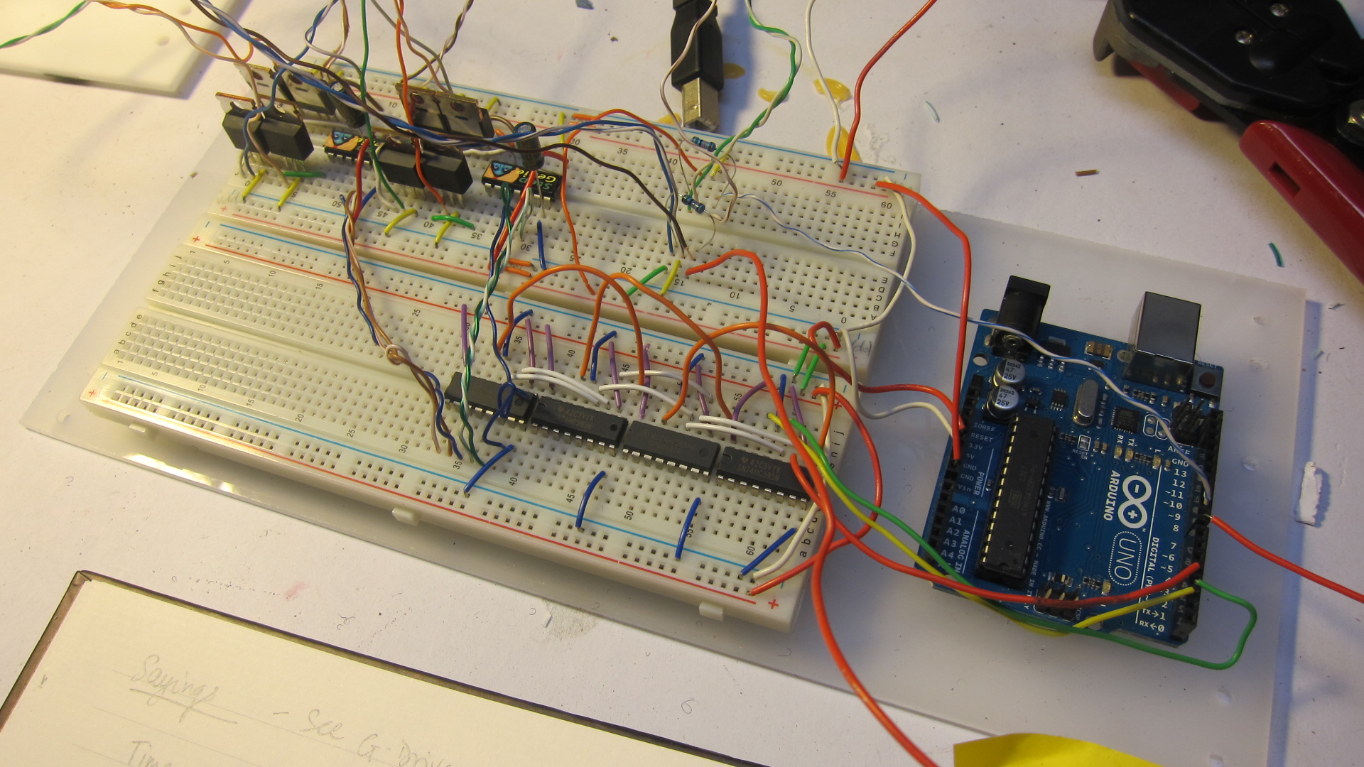 |
The general outline of the circuit is simple. Because the clock will have stepper motors, solenoids, LCD displays and LEDs, a lot of digital out pins are needed. Definitely more output pins than Arduino Uno has! The obvious solution is to daisy-chain some shift registers. By adding four shift registers, I get more than 30 pins that are addressable. Check out my code to see how you read and write to the individual pins.
|
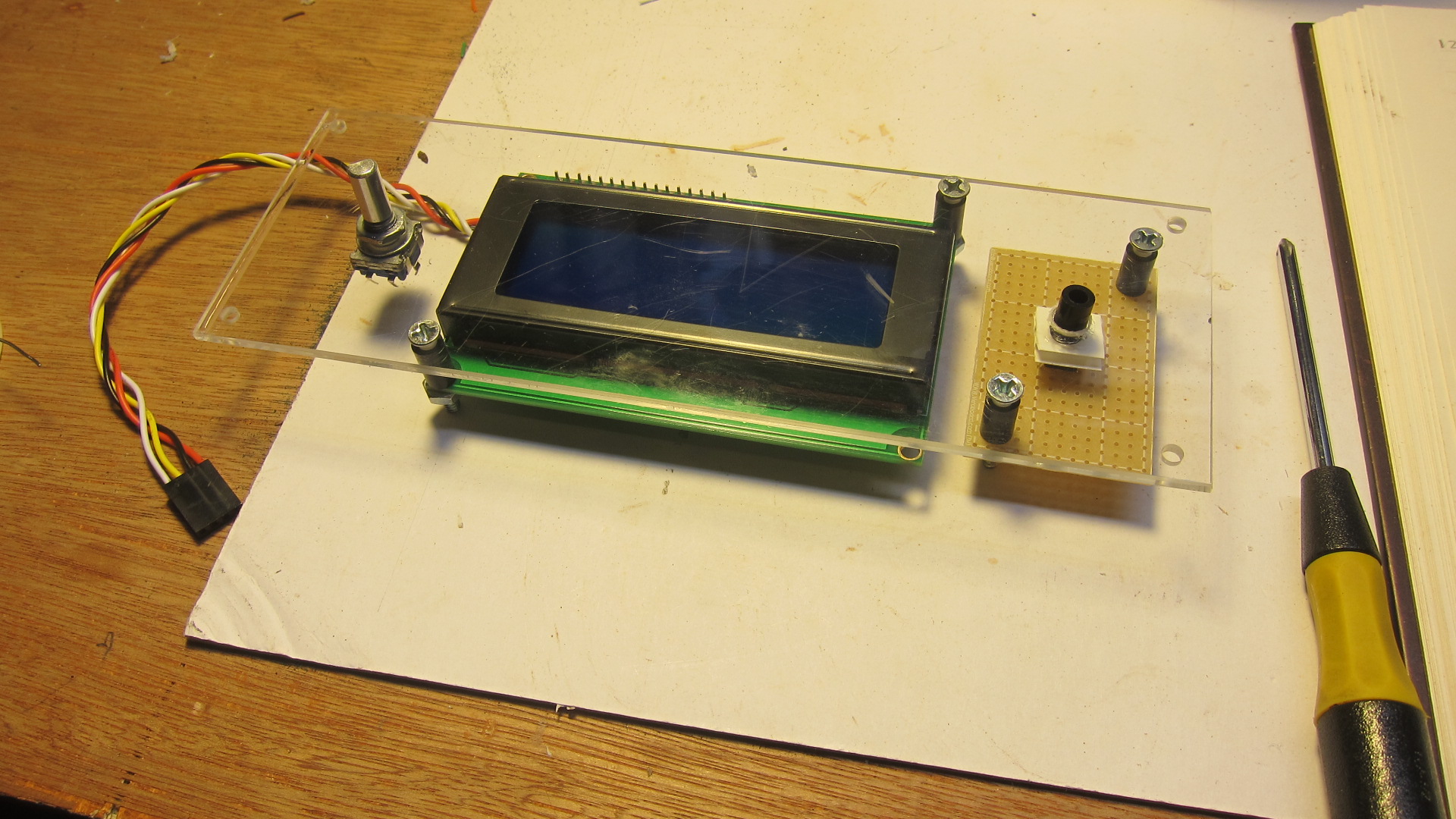 |
Here's the control panel under construction. This will be mounted inside the clock case. It has three components:
- A rotary encoder, which senses when the dial has been turned clockwise or anti-clockwise, and also when it has been pushed in. I will later write software for a menu system that allows the user to scroll through options and "push to select."
- Four-line LCD to display clock information and options from the menu. Uses the I2C protocol so doesn't use many of those rare Arduino pins.
- A single button, which I'll later use to implement a "mute" feature to stop the clock from making ticking or chiming sounds.
|
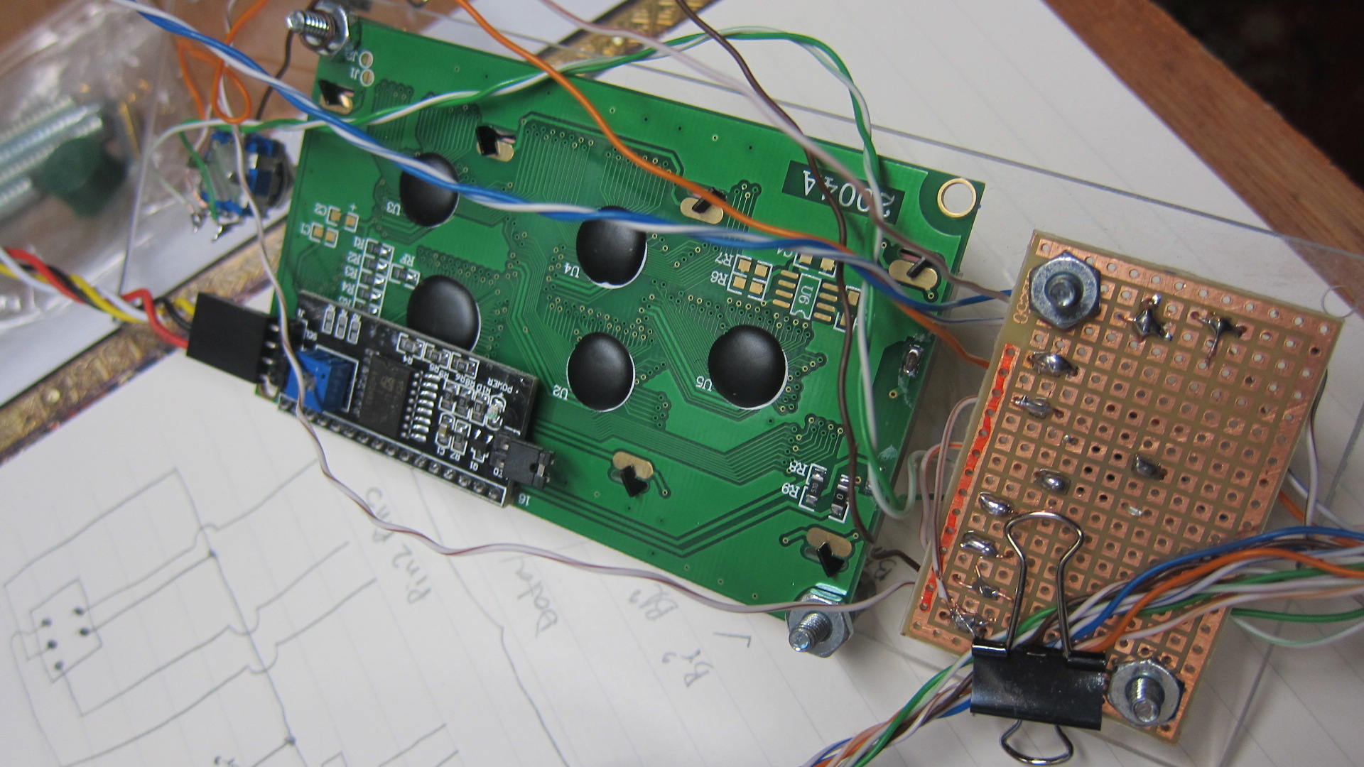 |
The rear of the control panel. The wires are from a Cat-5 (Ethernet cable) bundle. Cat-5 bought in bulk rolls is cheap and useful to help cut down on random strings of wire all over your project.
|
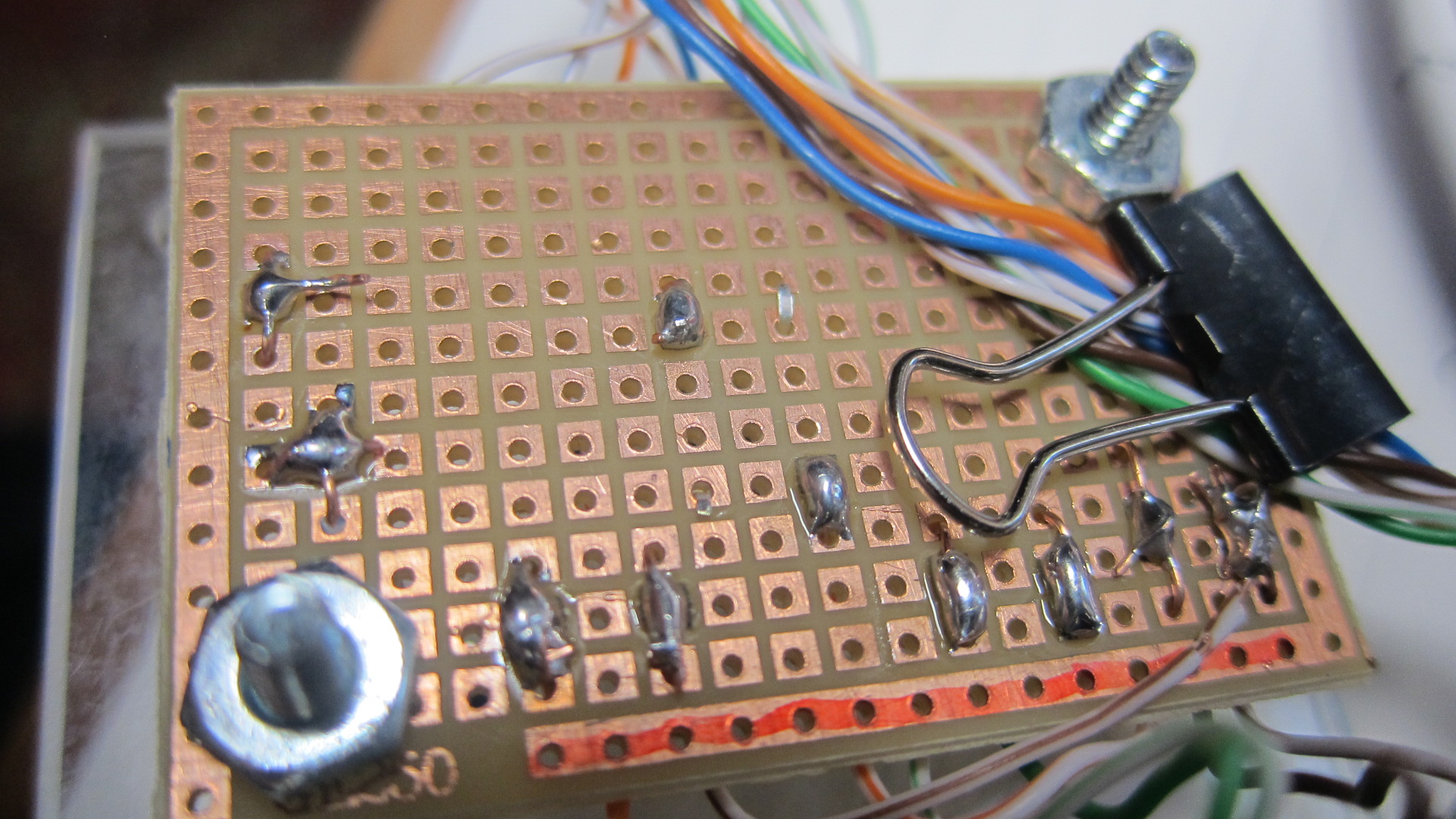 |
At some point I picked up a batch of these small prototyping boards; they've come in really useful for smaller parts of the circuit. In this case, this is the back of the control panel where I have all the connections congregate before heading down the Cat-5 bundle back to the main circuit.
|
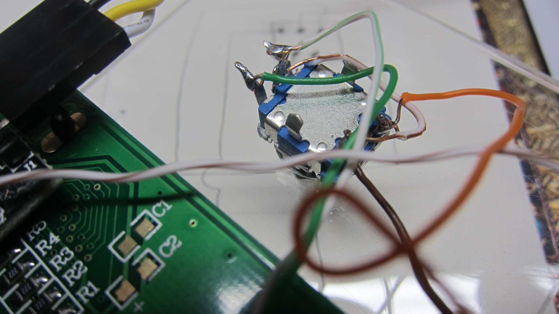 |
The rotary encoder uses 3 wires to detect rotation (check out the code, which in turn uses an interrupt to sense when the dial has been turned). Another 2 wires are part of the encoder's "push to select" - so it's a simple momentary button.
|
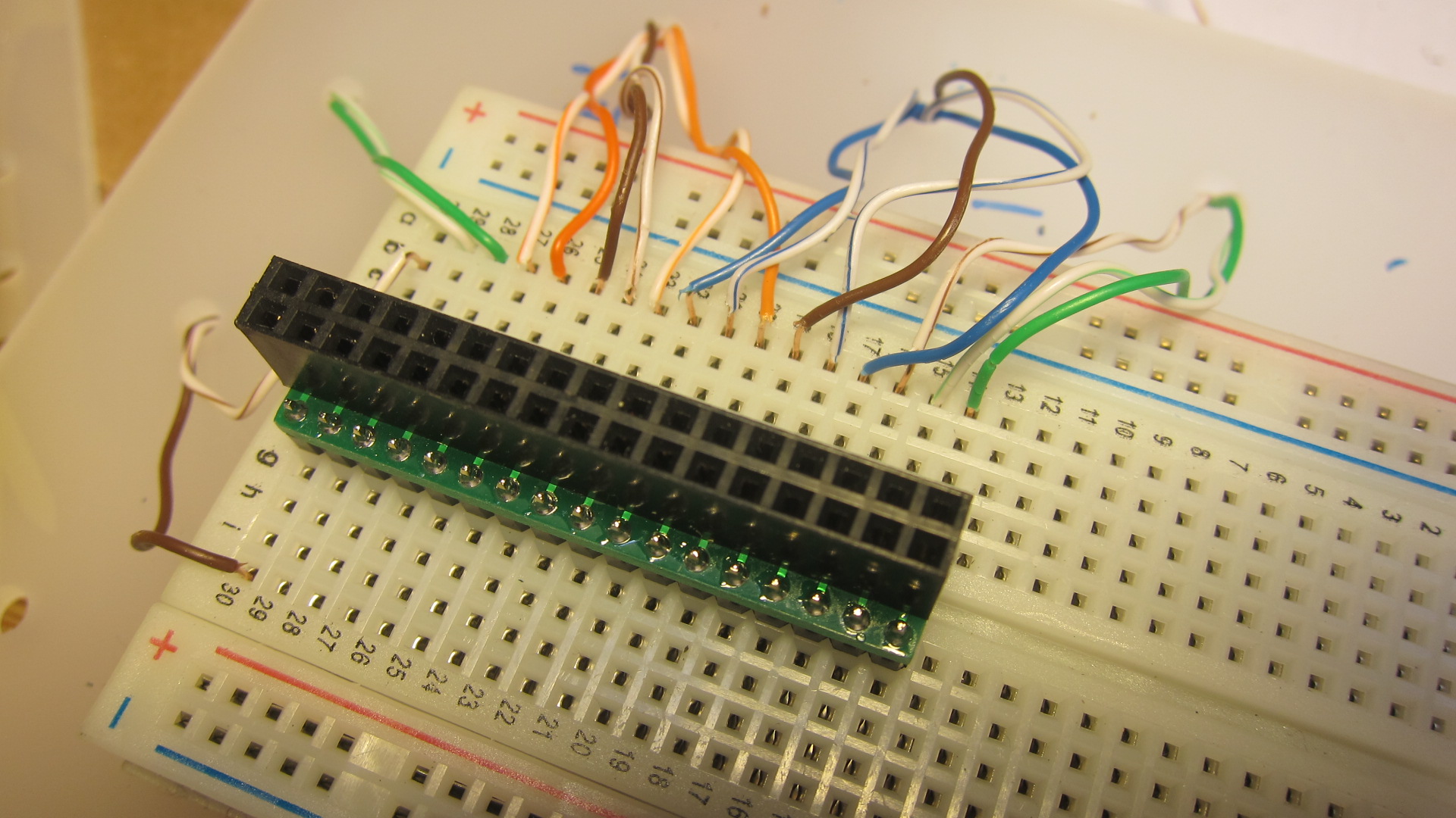 |
My calculations showed there would be a lot of control wires heading between the Arduino circuit and the movement (where the hands and dials are). Each motor needs 4 wires, and the hall effect sensors need 3. Even when you merge 5v, 7.5v and ground wires, this clock would need at least 28 connections. Instead of Cat-5 cable, which only has a bundle of 8, I opted to use 34-strand ribbon cable. I found these great adapters, which plug directly into a breadboard.
|
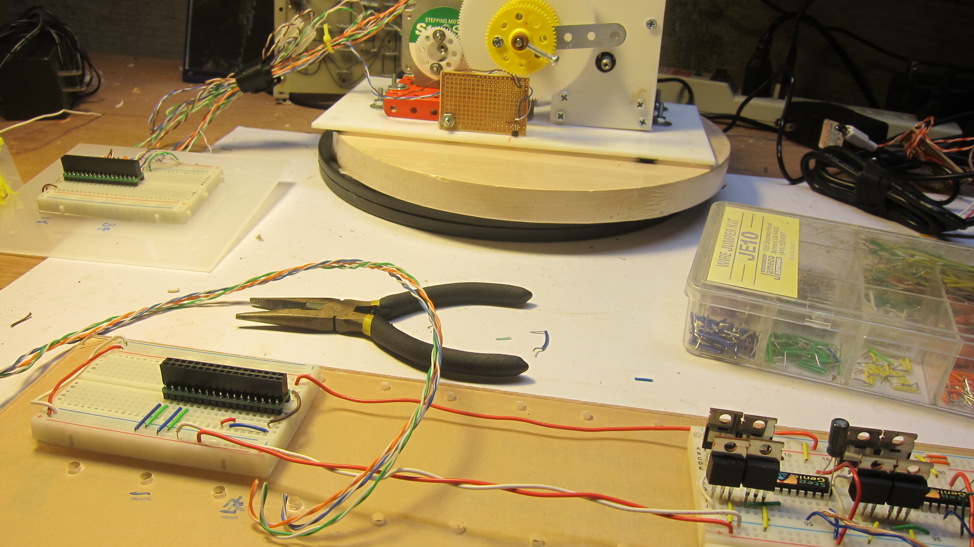 |
I'm beginning to lay out the circuit. Because I'm using breadboards, I have to put extra effort into making all the connecting wires flow in logical ways, with lots of 90 degree turns. I'm not building this clock with a soldered proto-board, or etching PCBs, because I'm making this circuit up as I go along. There were plenty of circuit-reworking sessions after this picture was taken!
|
 |
I have the LCD soldered-up and showing the time.
|
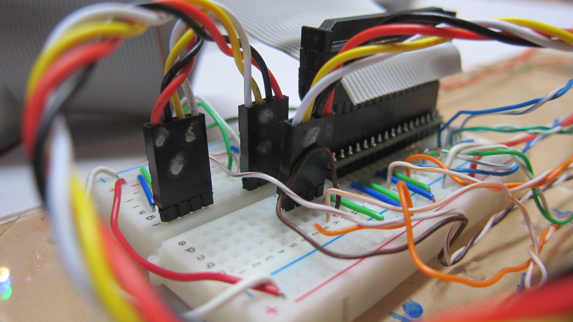 |
An example of more cable management. I found these nifty four-wire connectors which help reduce the strands of single wires reaching across the clock to its components. Helps keeps things tidy.
|
 |
The RTC (Real Time Clock) where the date and time is kept, even when the power goes out. These RTCs work on the same I2C line as the LCD. Check out my code to see how to set and read the clock. After building many Arduino clocks, I've decided the cheap RTCs that cost $3.95 aren't that great because they run fast or slow (due to cheaper components like the oscillating quartz). So now I only buy them from Adafruit.
|
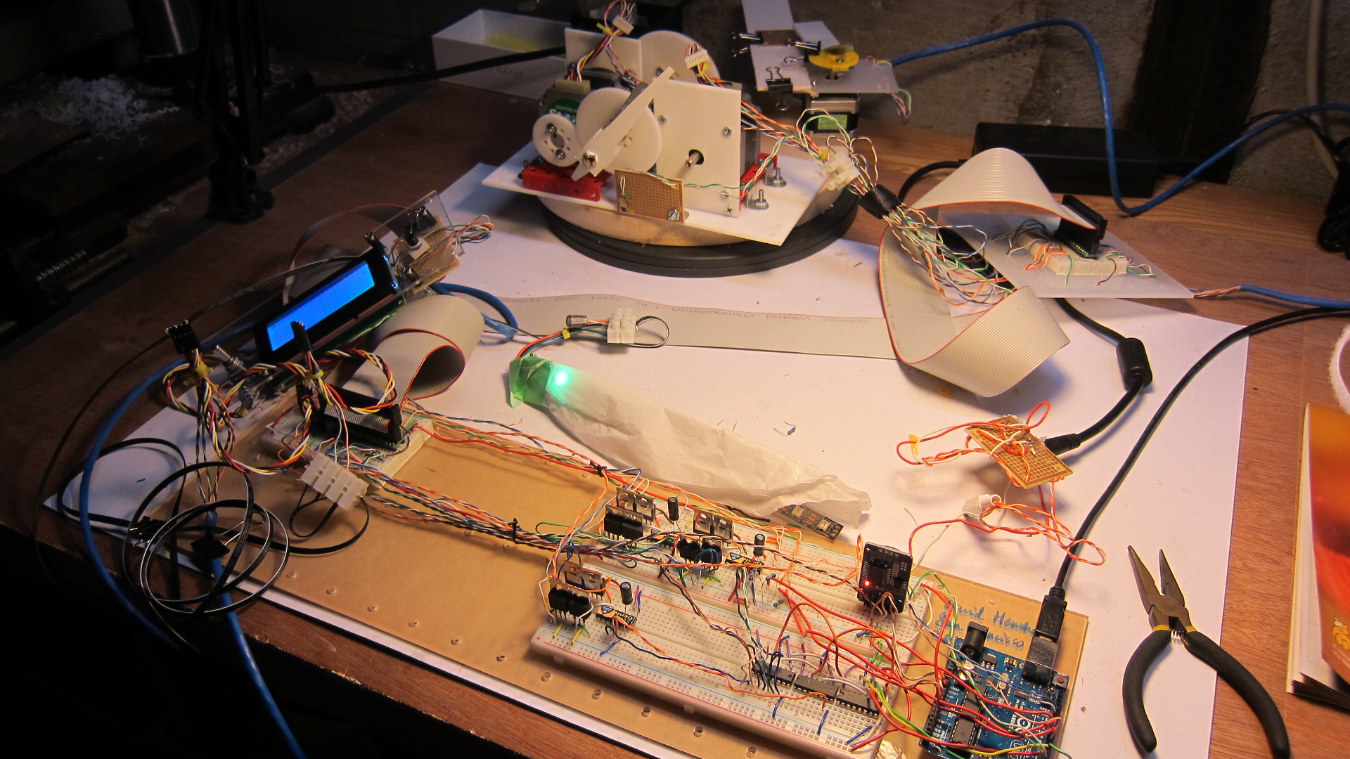 |
The circuit is expanding, and I've also added a strip of programmable LEDs, often called "Neopixels." Each of the 12 lights in this strip can be individually turned on, and set to any color. The idea is this will be used as part of an activity panel inside the clock, so you get a visual overview of what is happening.
|
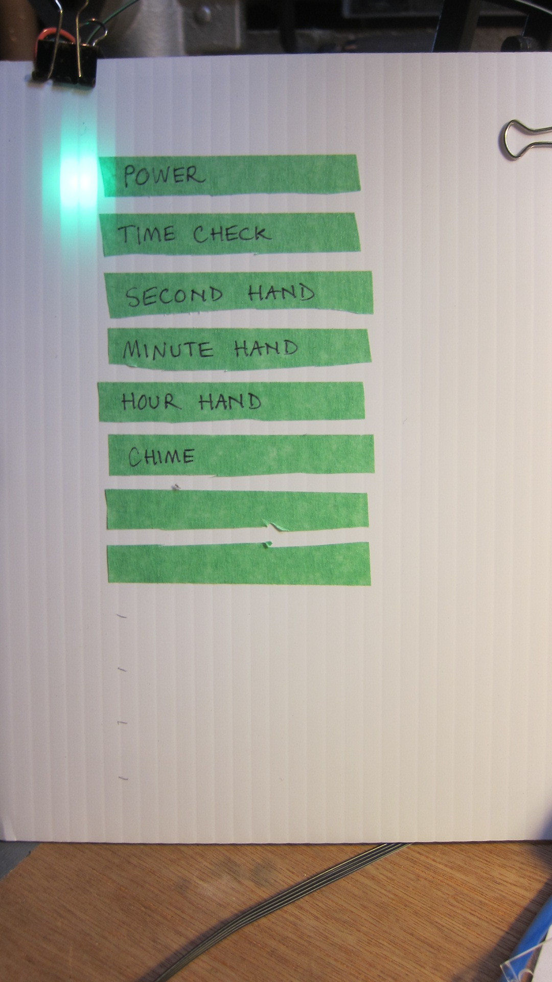 |
An early prototype of the activity panel.
|
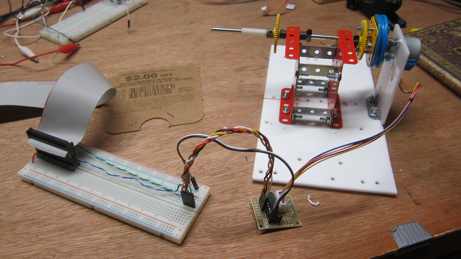 |
All those heavy stepper motors were too much - really heavy and quite loud when they turned. After all, they're designed to move big and heavy loads, not a clock hand that weights less than a pencil. I found these amazing geared stepper motors on Amazon. They're cheap, come with a simple controller board, and run on low voltage. They are also very small, which makes my clock movement much smaller.
|
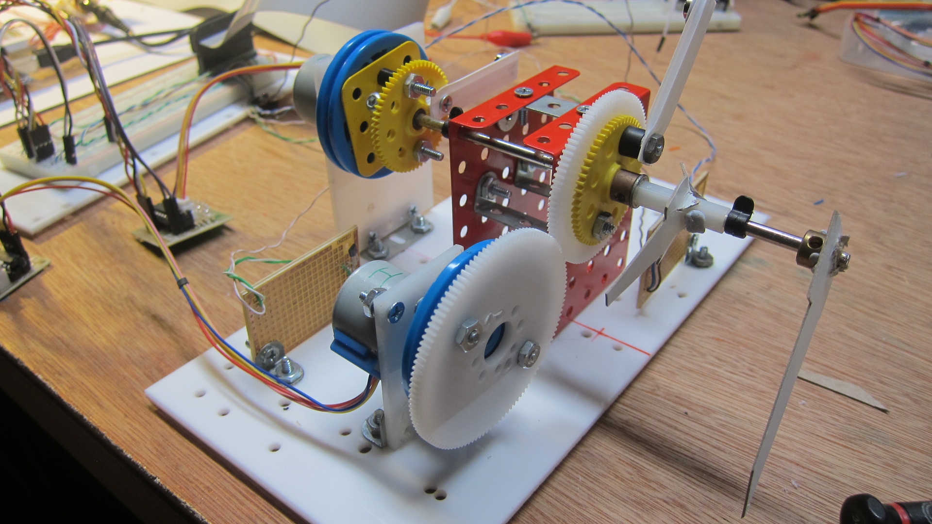 |
I've been able to make a new, lighter, smaller movement with the new motors. Smooth and quiet.
The core program logic is coming along well, and works like this:
- One full rotation of the minute hand (and other hands and dials) is 360 degrees.
- The stepper motor requires 4,096 physical steps to rotate once. It's so many steps because this is a geared motor - slow, but high torque. The code advances by 8 steps for each stepOnce() function in the code, so that's 512 calls to this function to rotate the motor once.
- Let's say the time is 20mins 0secs. The minute hand should be exactly 33.333% through a complete revolution. That's because 20mins/60mins= 0.3333.
- Actually, it's a bit more complicated than that. Because I want the minute hand to rotate almost continually, not just once a minute, I need to take into account the seconds. In one hour, there are 3,600 seconds. At 20mins past the hour, 1,200 seconds have elapsed. So that's how we end up at 33% (1,200/3,600).
- So at 20mins 0secs, the motor should have completed 33% of its steps through this hour's turn. So it should be at step number 170 (33% * 512).
- Shortly thereafter, time advances to 20mins 3secs. In this hour, 1,203 seconds have elapsed. So the stepper motor needs to have completed 33.4166667% of its turns, which is 171 turns. So stepOnce() is called, the motor advances slightly, and the minute hand continues its slow rotation.
|
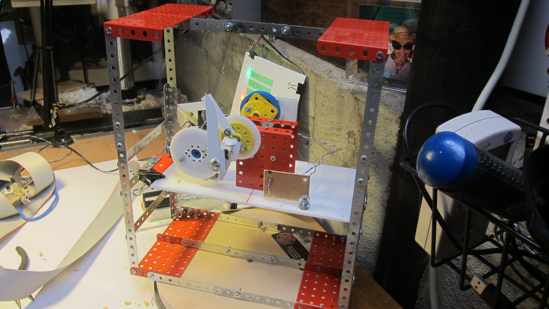 |
I started building the frame for the movement (the clock face will sit in front of this). So far I've just got the hour and minute hands mocked up.
|
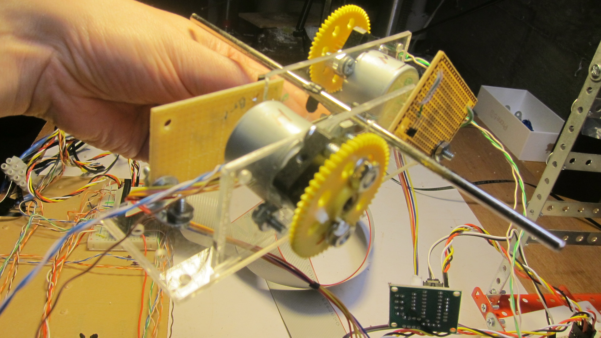 |
In a further iteration, I rebuilt the movement. With the smaller motors I can re-imagine the housing. So now it's half the size it used to be.
|
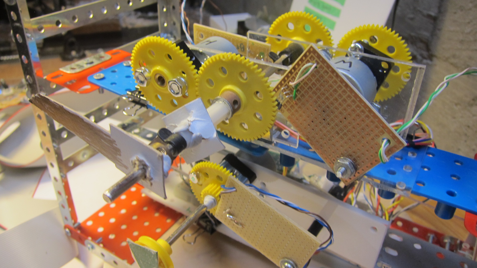 |
The new housing in the frame. I have also added the hall effect sensors (the brown boards). Below, you can see the first iteration of the calendar dial.
|
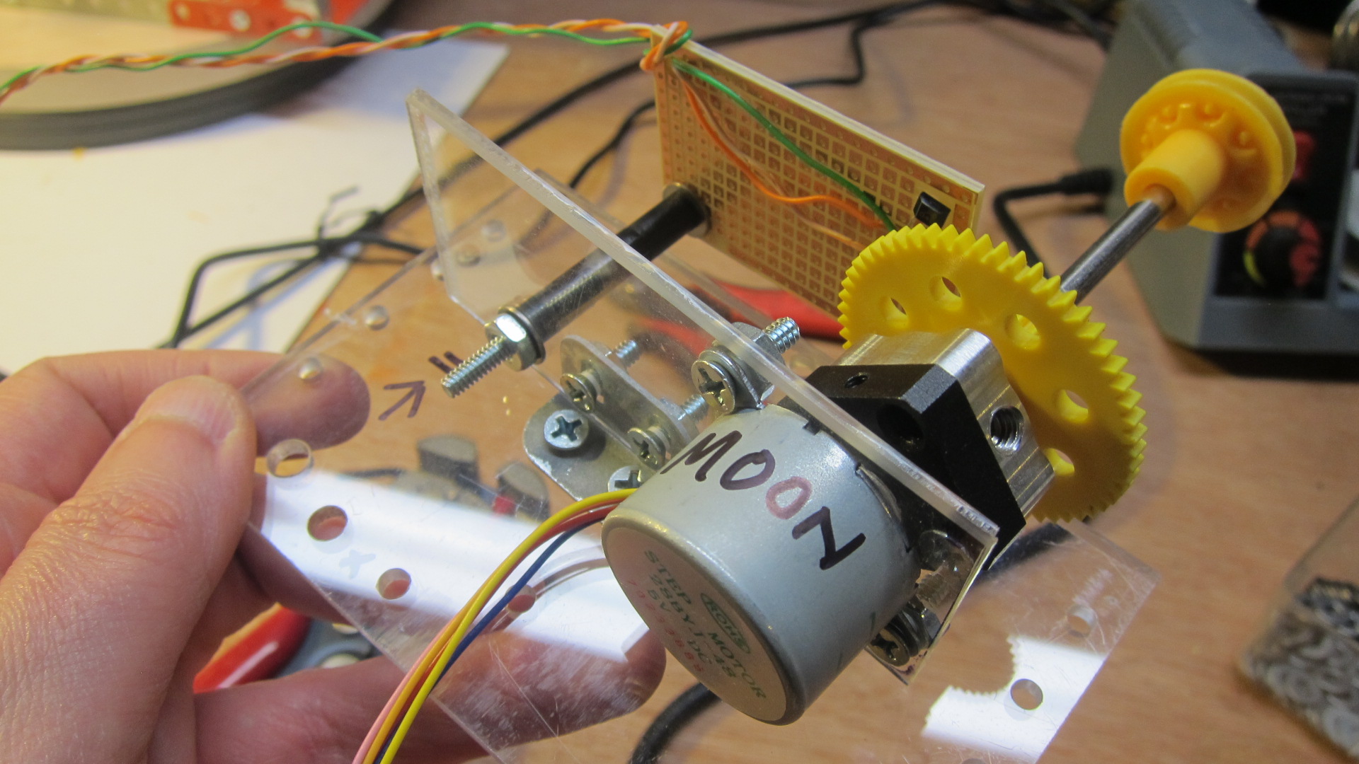 |
I knew I wanted a clock that had a moon dial (keep reading to learn more about that). I pre-built the mechanism, and here it is. I tend to use acrylic cut to the right size, and spare bits of Meccano to connect things together.
|
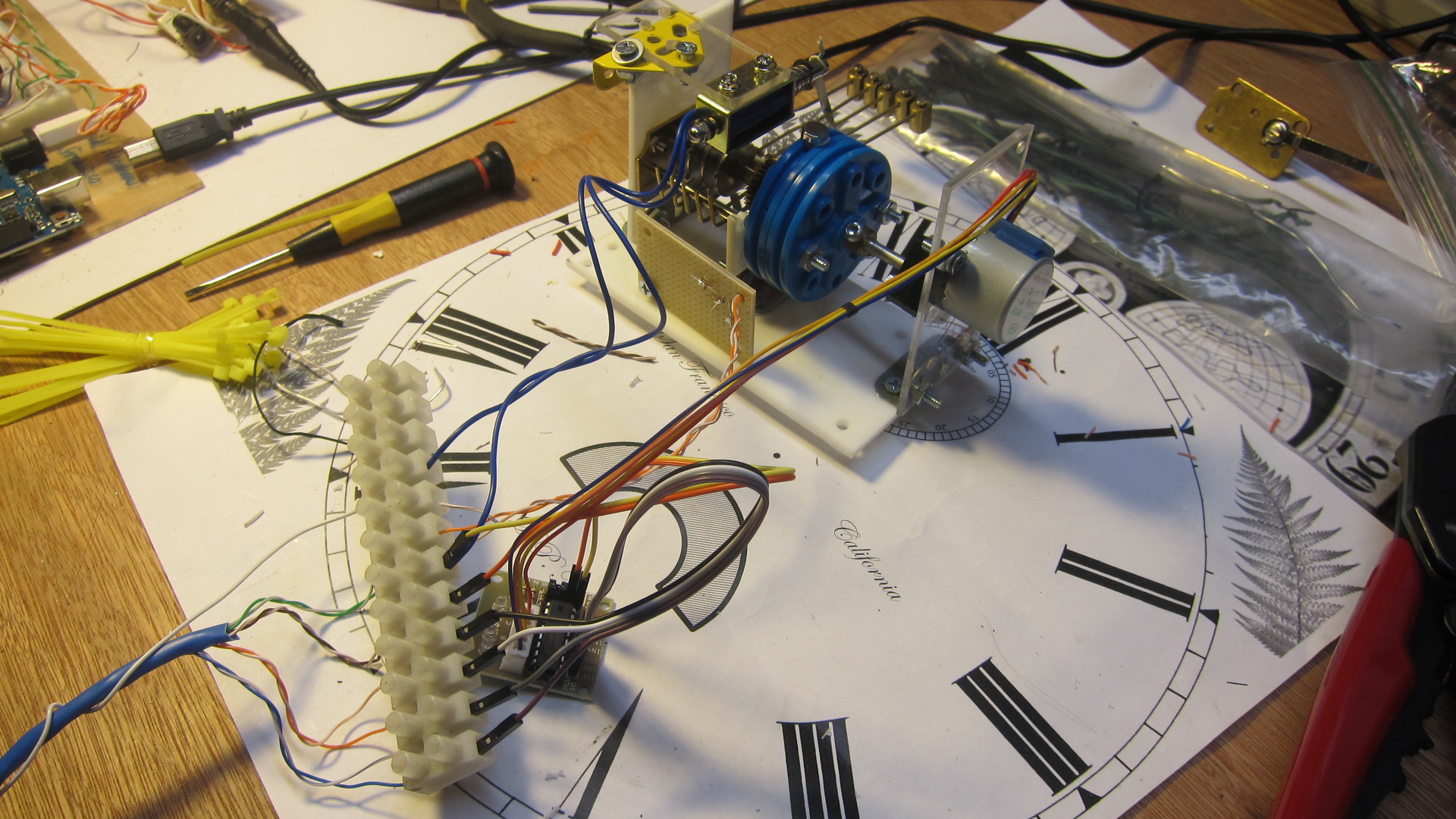 |
Version 2 of the chiming mechanism. I bought a 5-rod chime from eBay, and figured I could use a stepper motor to rotate the cams, which in turn hit the chime rods. Separately, a solenoid is used to pull back three of the hammers, and release them in unison - this creates the "gong" sound.
|
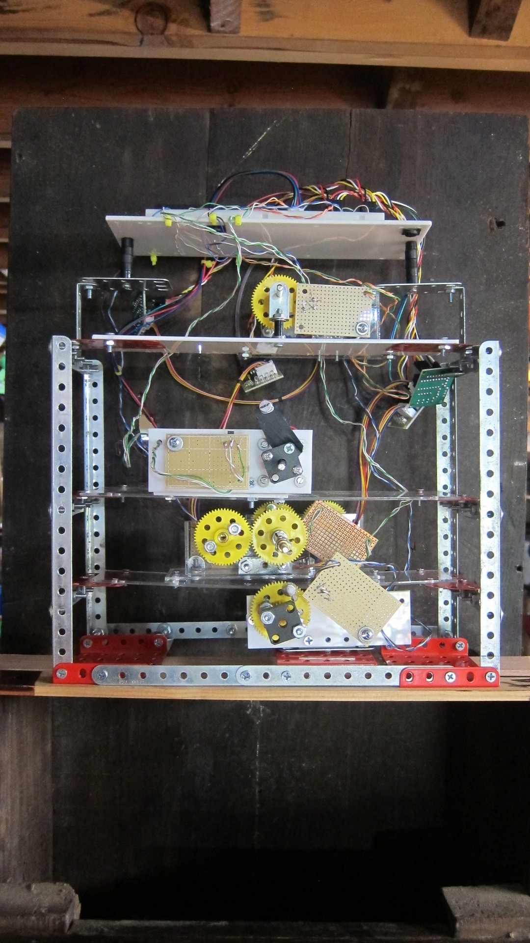 |
The frame's taking shape - from the bottom, you can see the calendar dial mechanism, then the hour/minute hand, above that the second hand, and at the top the moon dial. By this stage, I had found an actual clock, so was able to start fitting the mechanisms precisely to the openings in the dial. This required millimeter-level precision, so took a lot of monkeying around.
|
 |
Another view of the frame in-situ.
|
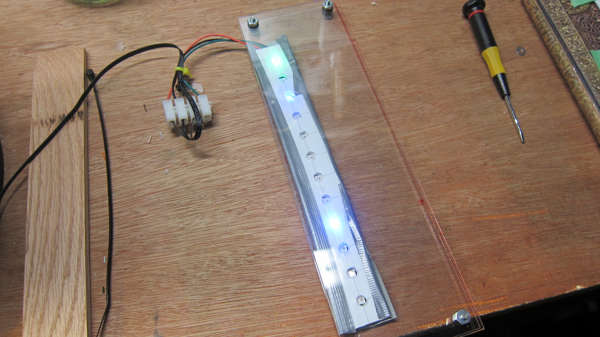 |
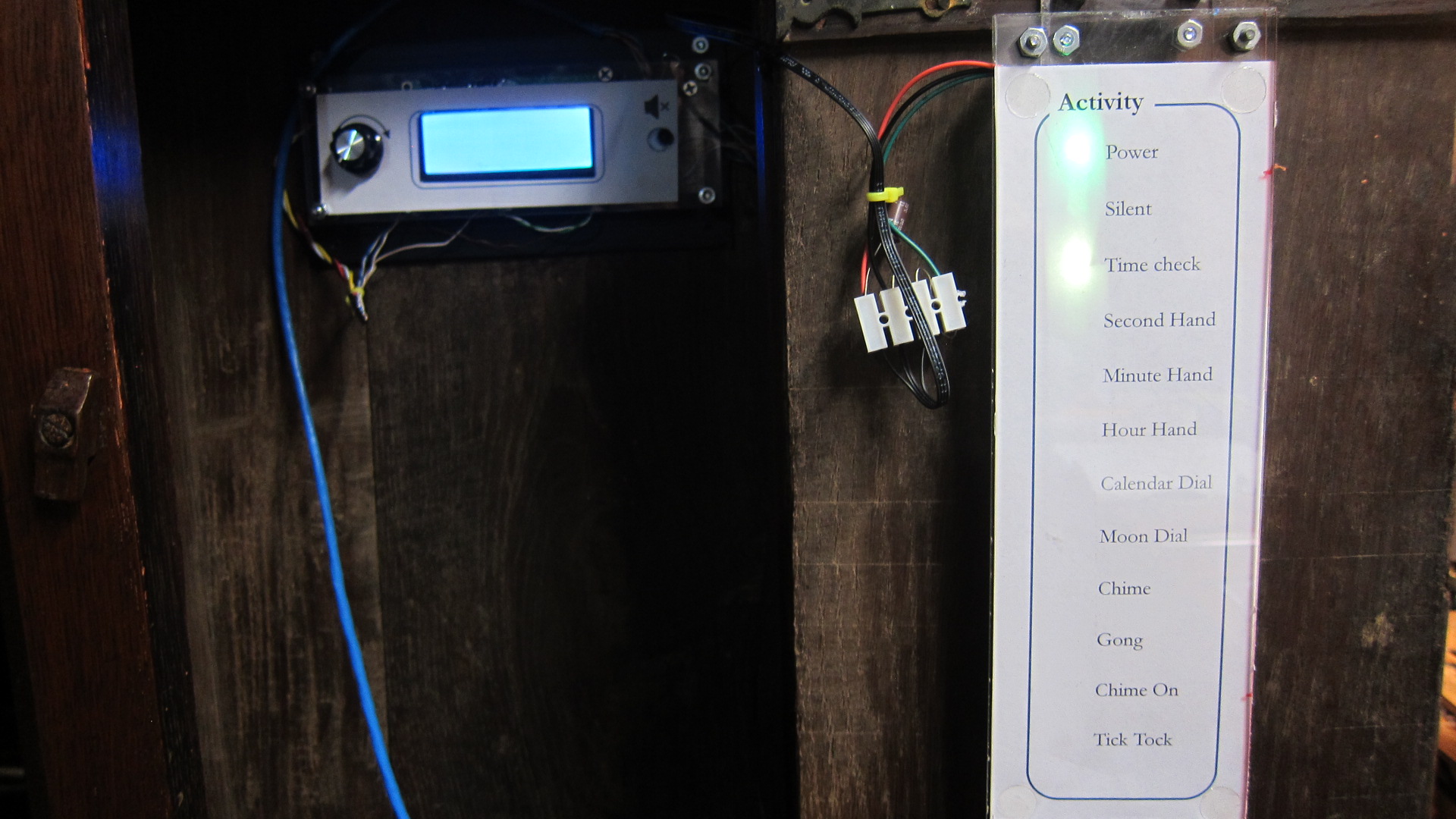
The Activity Panel starting to take shape. The LCDs are held in place behind a piece of plastic with holes in it to stop the colors from bleeding too much.
|
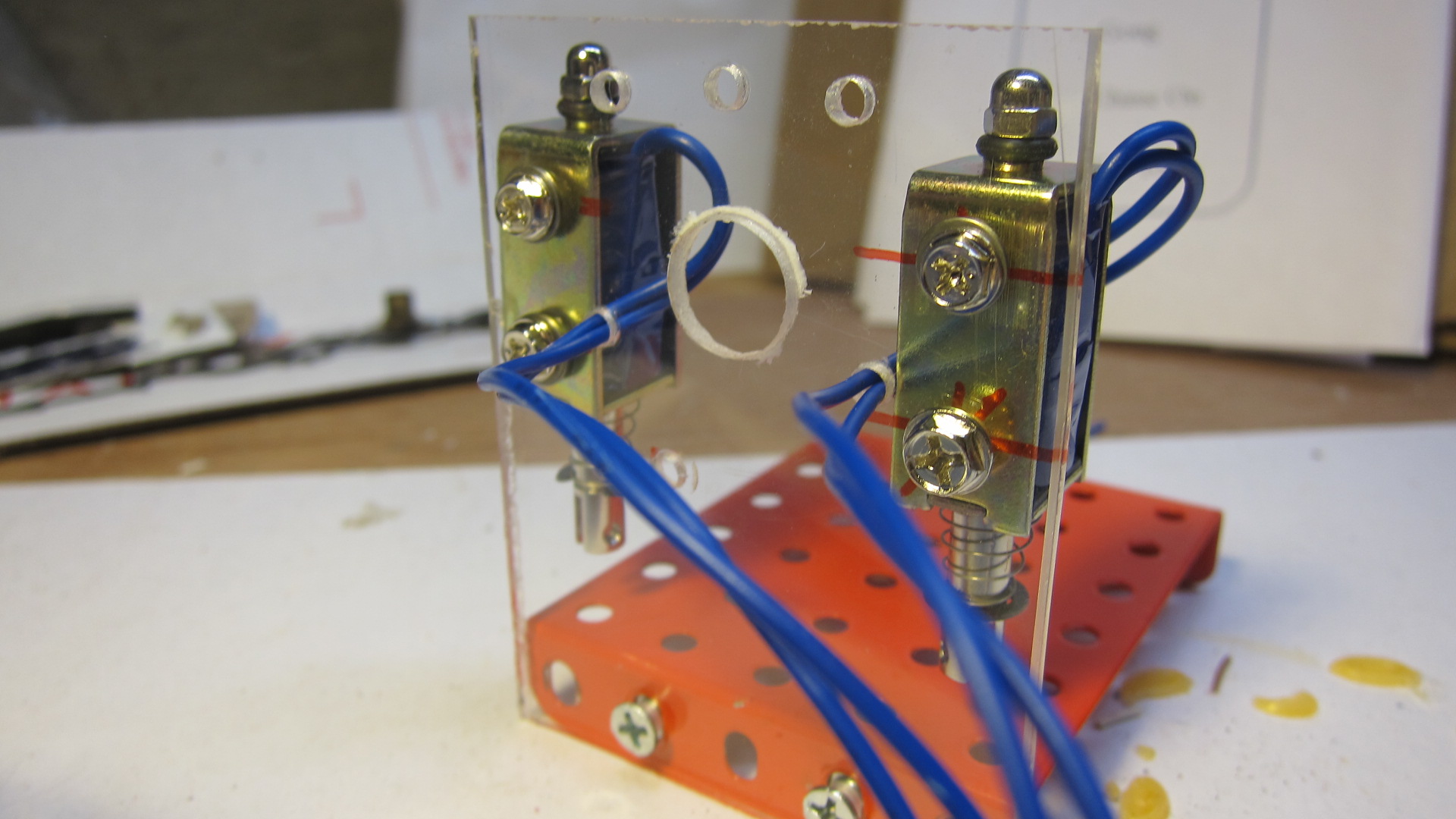 |
What would a clock be without a tick and a tock? Although this clock doesn't need a pendulum, it would be hard to justify going through all this work without hearing it tick. After much experimentation I built this two-solenoid contraption. By activating each solenoid in turn for a few milliseconds, you can approximate the sound of an antique grandfather clock. Because the "tick" and the "tock" sounds in a clock are a little different, I activate the solenoids for different durations (17ms and 25ms).
|
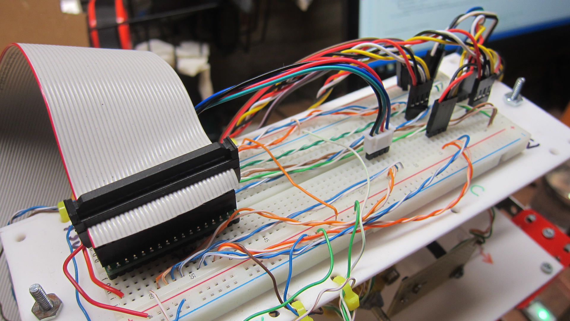 |
This breadboard sits at the top of the frame. The ribbon cable comes from the main breadboard and is then distributed across the rest of this board. Then, smaller jumper cables run to each of the motors.
|
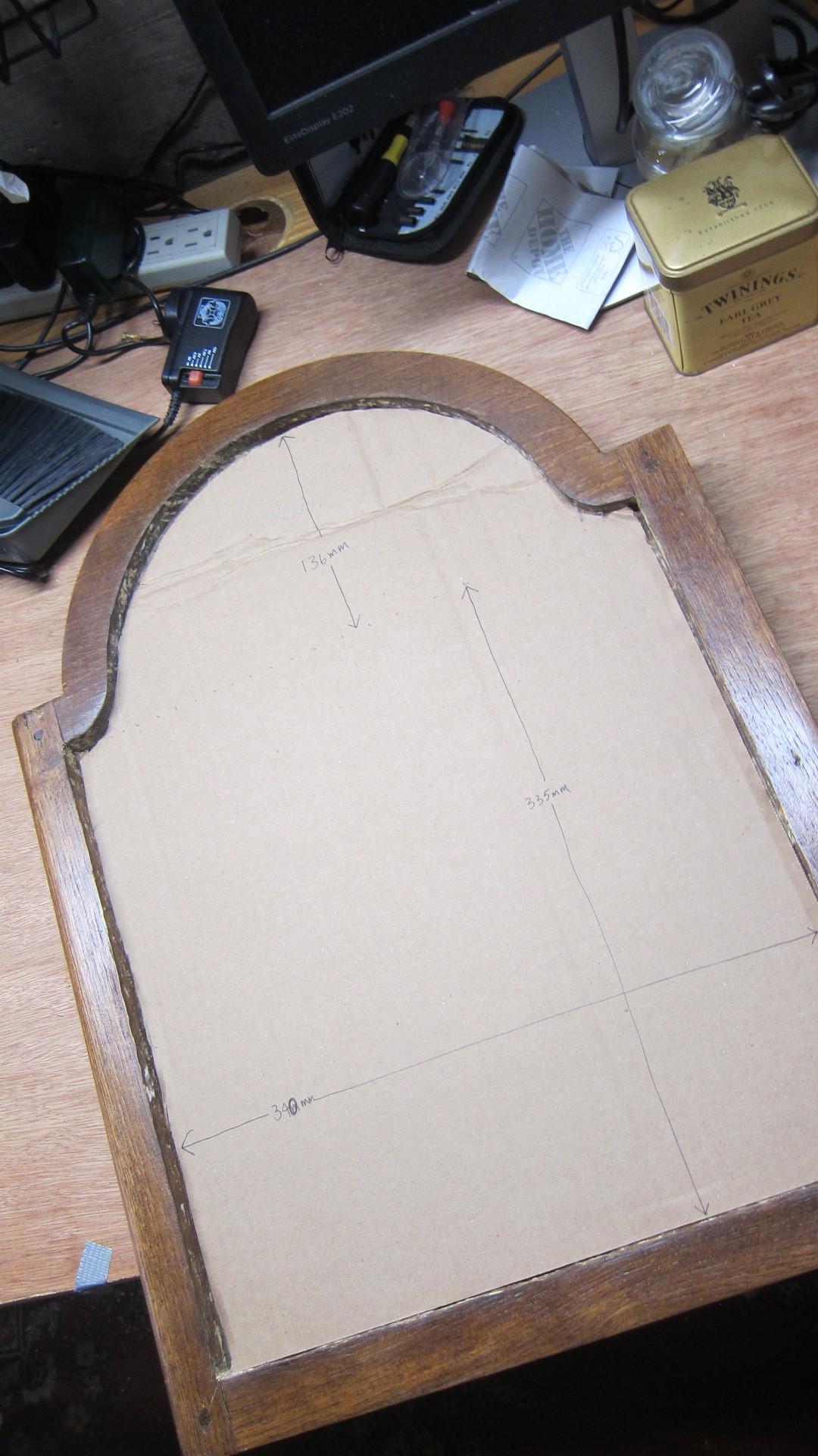 |
When the clock case was delivered, the glass on the front was broken. I removed the remaining shards and used a heat gun to remove the 170-year old putty. Here it is waiting for new glass to be installed.
|
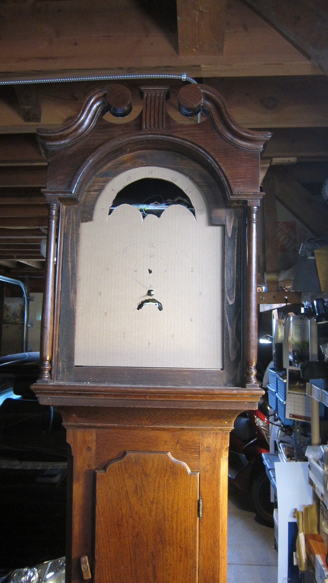 |
A test fitting with the movement in the case. Now it's starting - barely - to look like a clock!
|
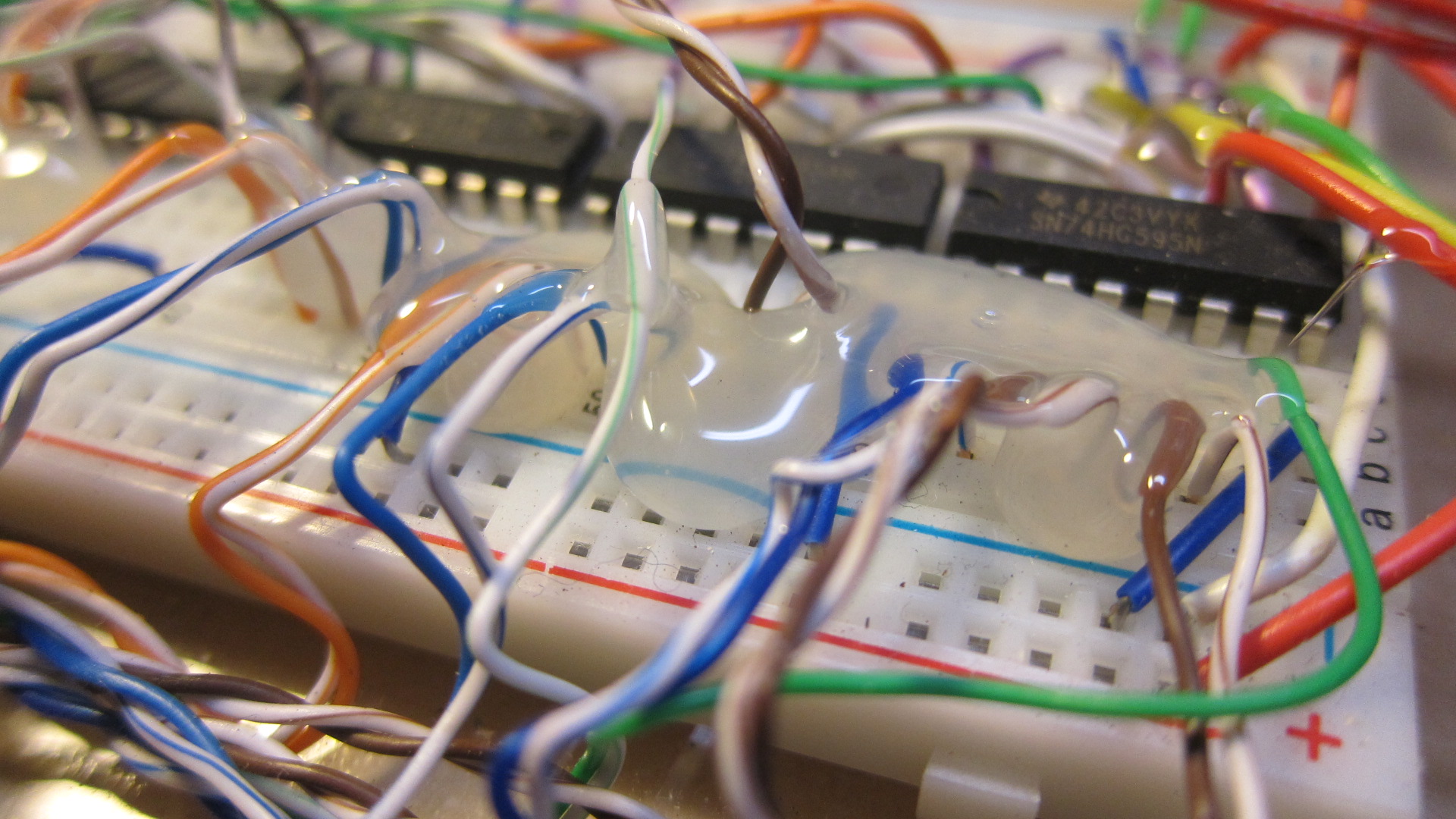 |
The circuit design hasn't changed much recently, so it's time to hot-glue all the wires into place.
|
 |
The clock mostly runs off 7.5v. A separate 12v supply is used for the chime solenoid. I could have used a single 12v supply and reduced it to 7.5v with a small circuit, but I was getting tired and wanted the simplest solution. This power panel is installed at the very bottom of the clock, with a single power cable that exits at the bottom of the case and plugs into the wall.
|
 |
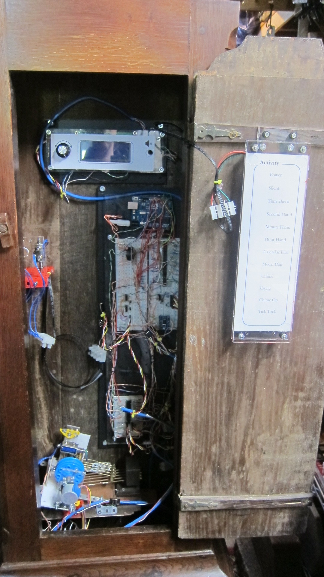
Starting to install components inside the clock.
|
 |
The control panel and main Arduino + circuit.
|
 |
Now with the tick-tock solenoids and chiming mechanism.
|
 |
A view down the inside of the case
|
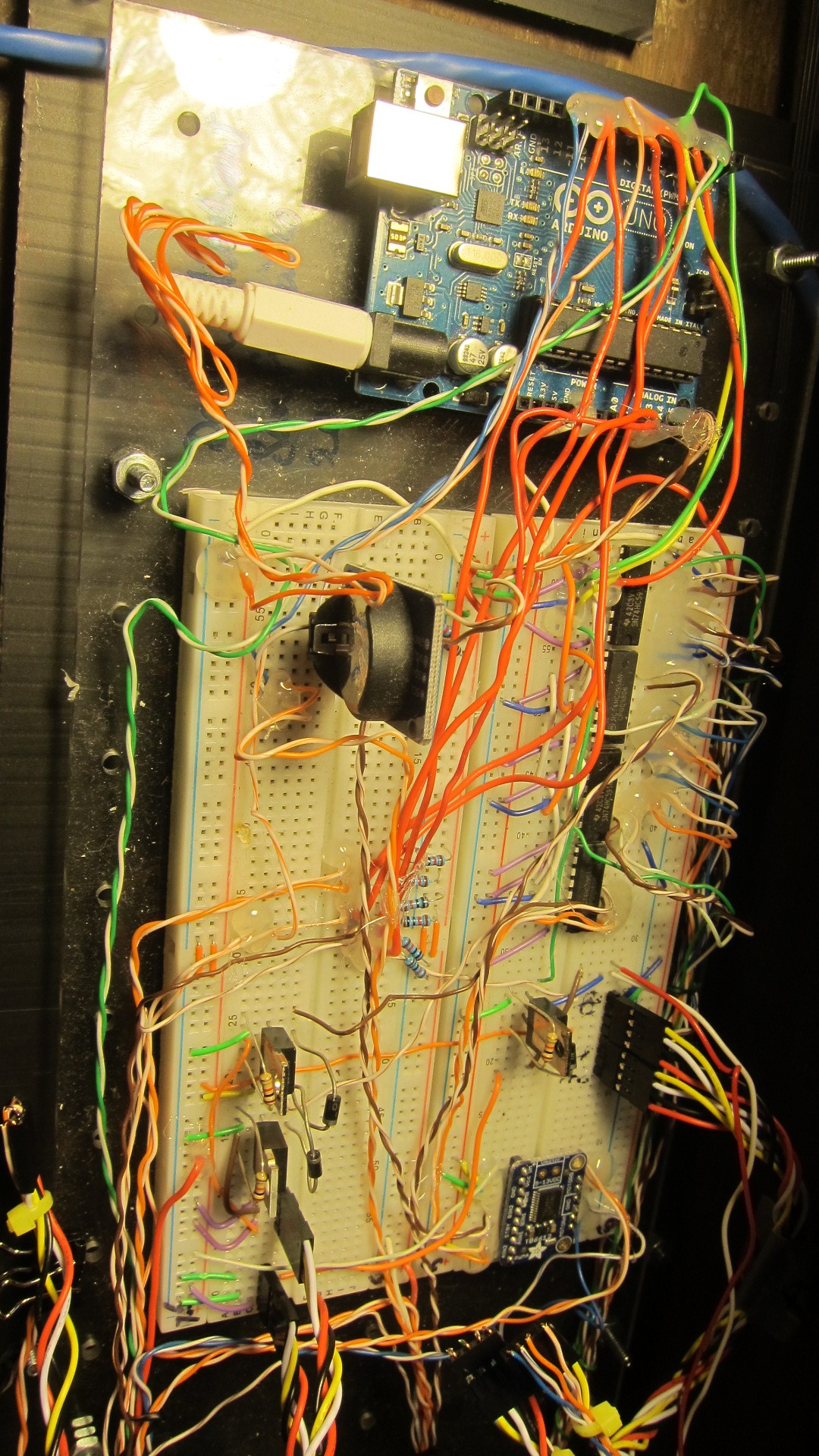 |
The main circuit.
|
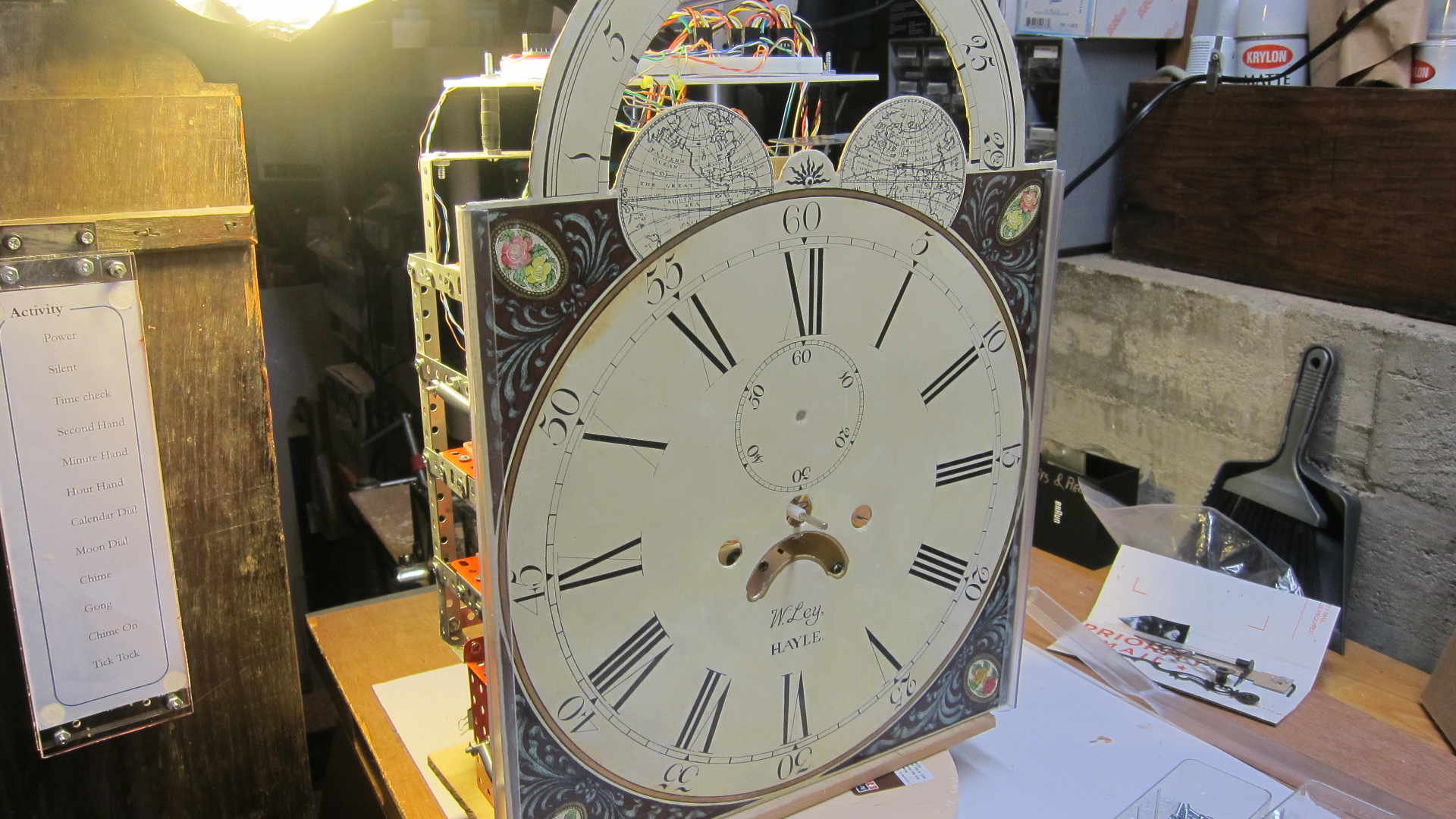 |
The clock I'm rebuilding was built in 1847. It has this absolutely stunning painted clock face, and it's in pristine condition. Here you can see the face resting against the frame. It took many hours to line up the motors in the frame with the holes in the face.
|
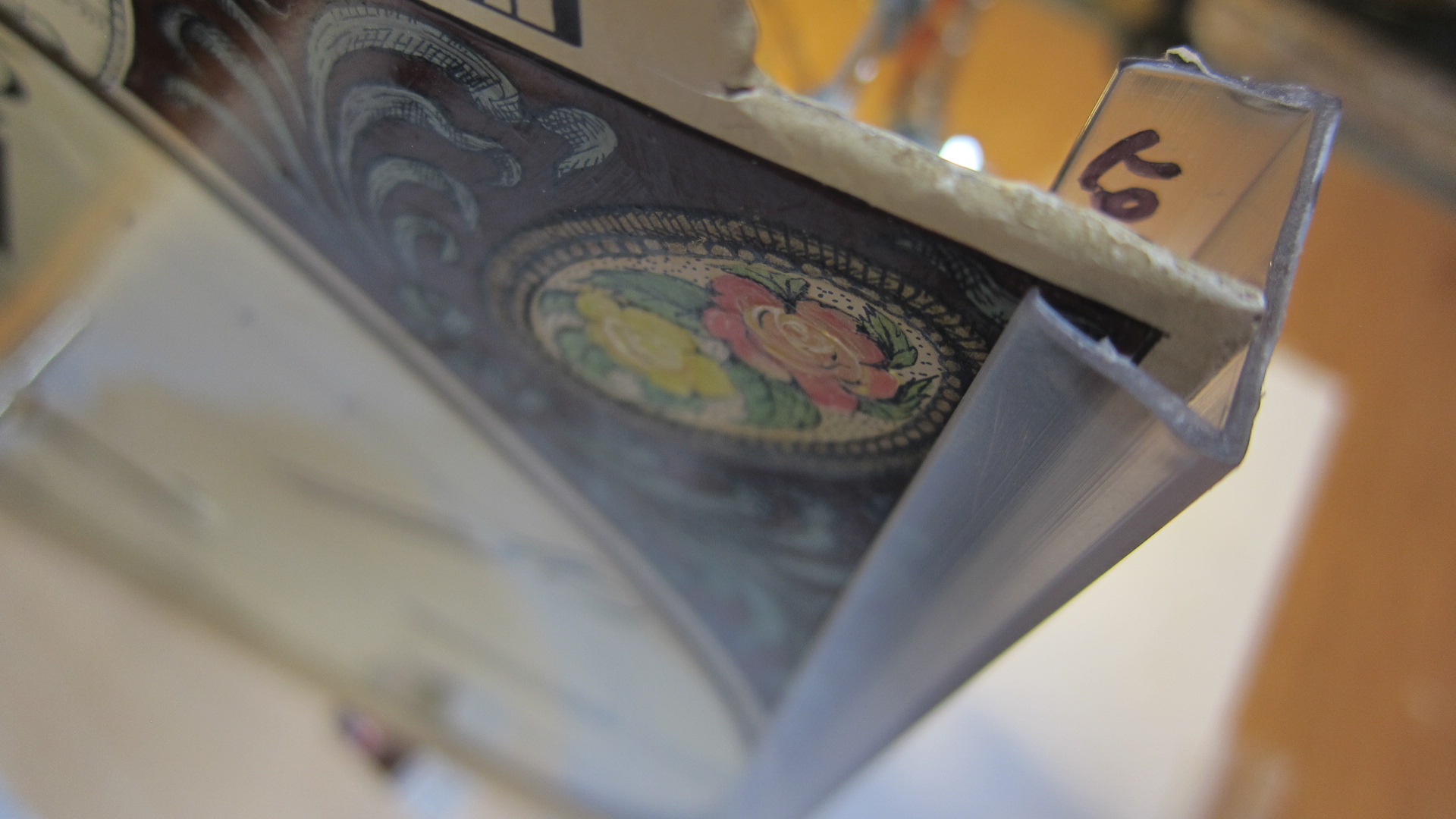 |
One challenge was how to "affix" the heavy, sheet metal face to the frame. I settled on this transparent plastic guide (an LED lighting bracket), held back by springs, that stops the face from falling forward. Elegant solution and simple.
|
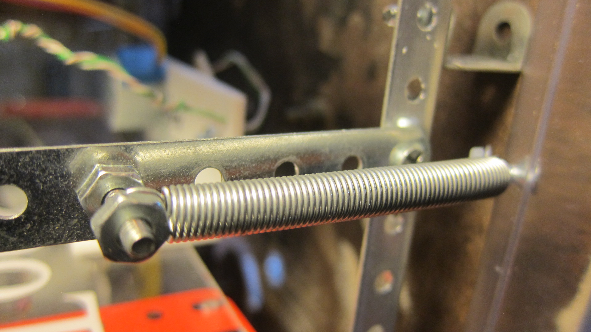 |
Four springs hold back the face, and they're connected to the frame
|
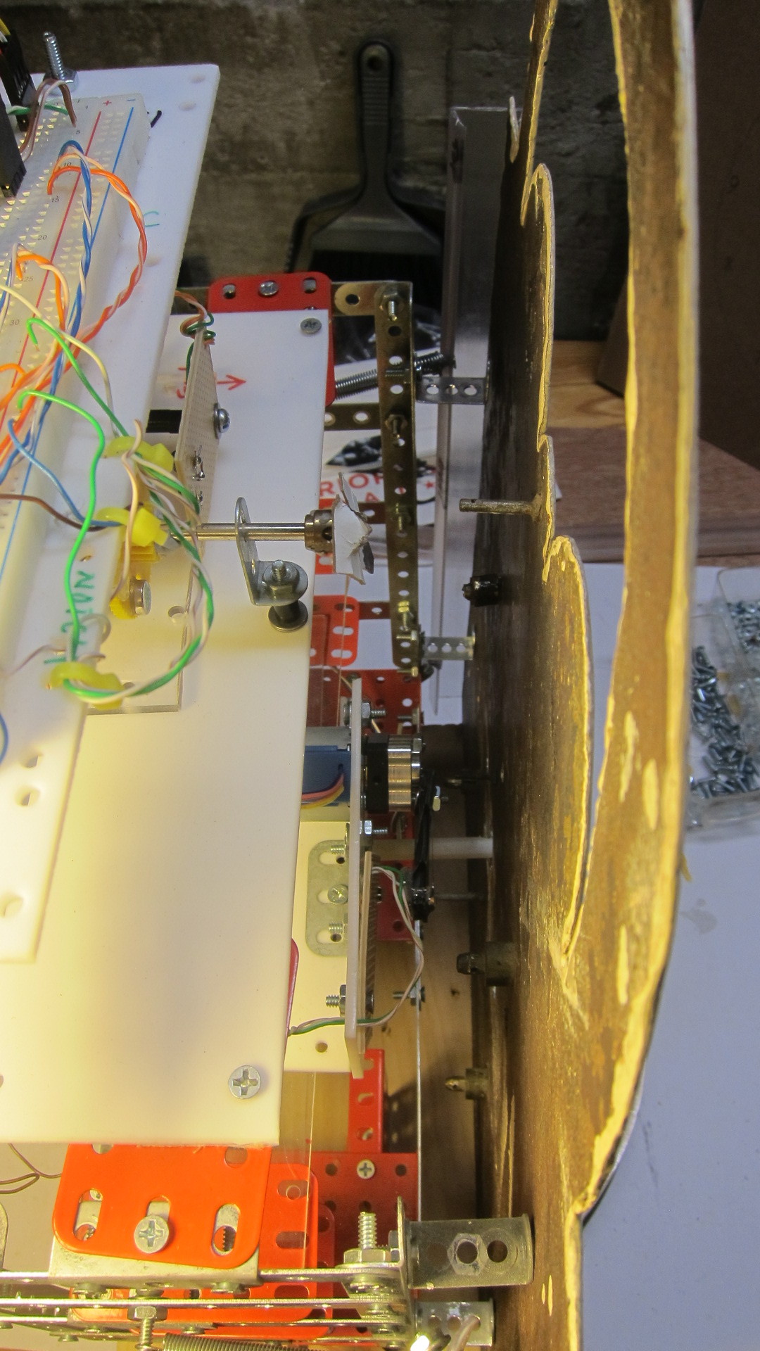 |
There's approximately a one inch gap between the frame and the face. The next big challenge is to connect each of the motors to their respective hands and dials in a very cramped space.
|
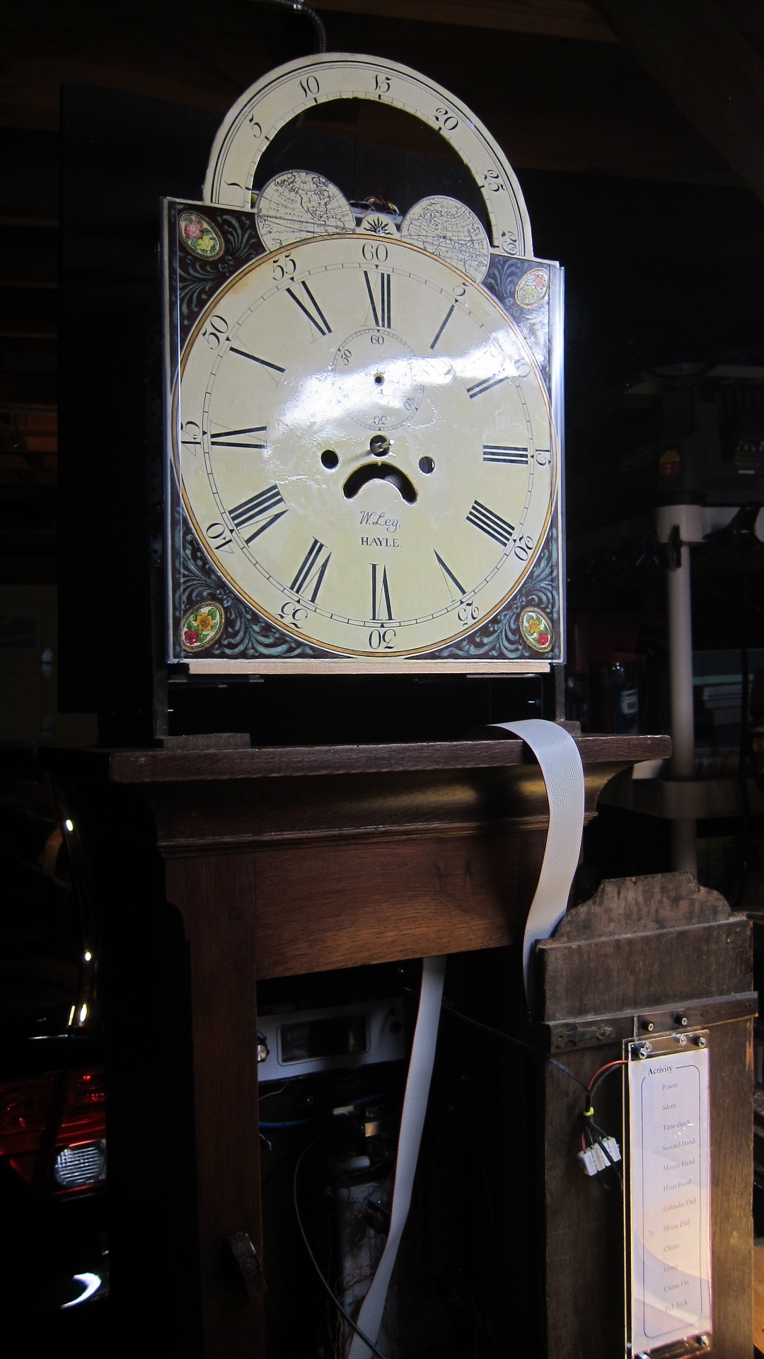 |
The frame, with attached clock face, seated at the top of the clock. Looking nice!
|
 |
The calendar dial in the original 1847 movement used a sawtooth gear to allow it to rotate to the correct date. My movement uses a motor. I connect the motor to the black hub via a flexible shaft. The hub has a set screw and fastens to the central shaft of the dial. I like how the dial is stamped with the manufacturer - "T.H.PRICE, BIRM(ingham)"
|
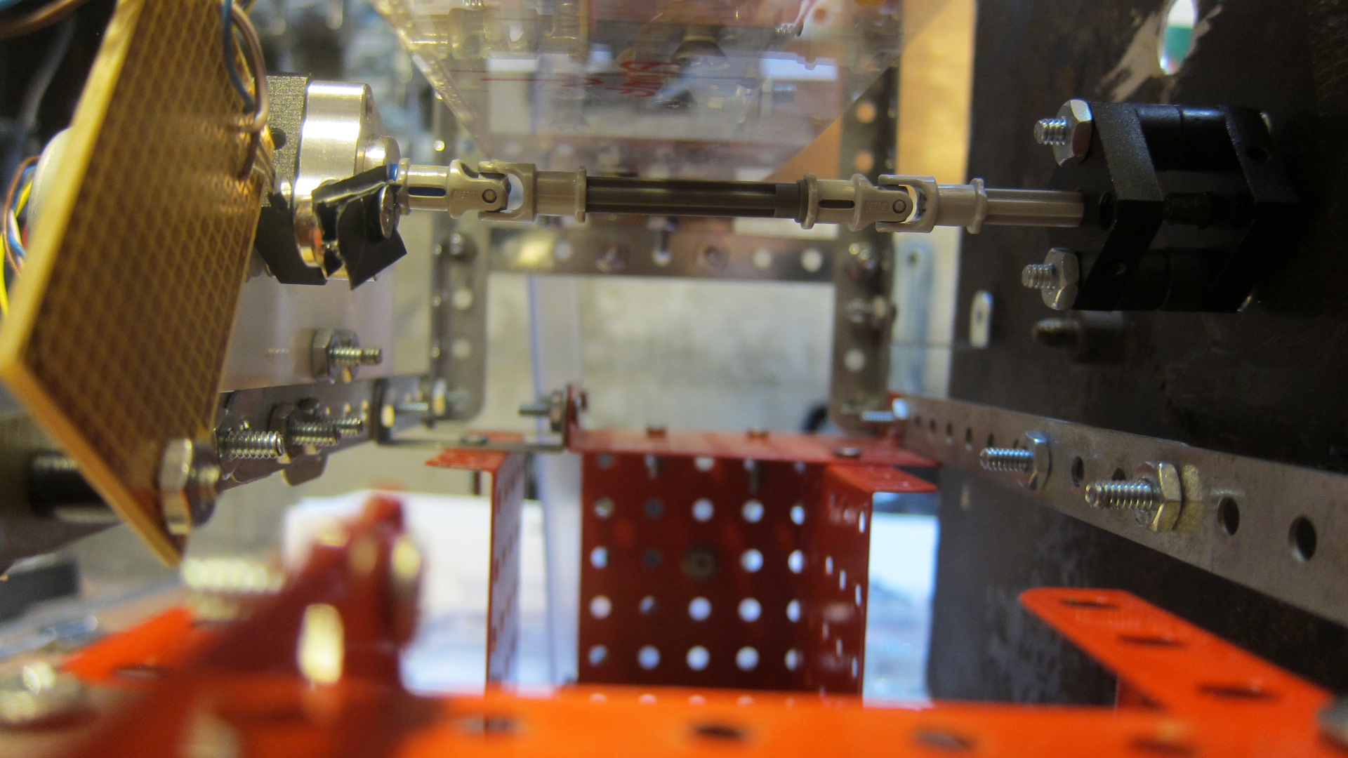 |
No matter how hard I tried, it was not possible to exactly align the motor shaft to the dial's shaft. I got close, but even a 1mm offset is no good for a rotating axle. So I used two Lego flexible joints, which I bought on eBay, to connect the parts. Problem solved!
|
 |
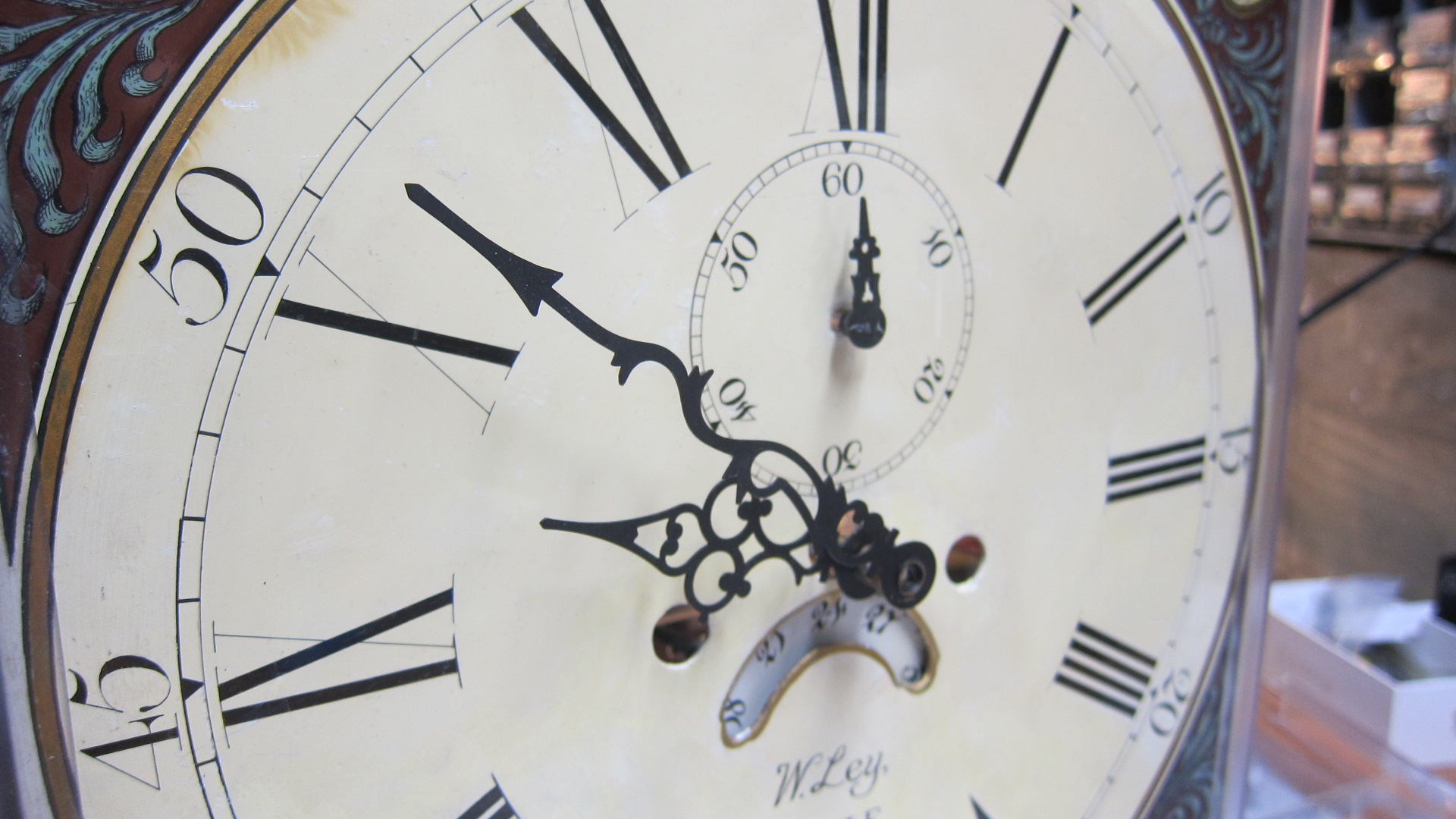
We're getting close, now! The clock face has the hands and dials installed. You can see here it was built by a "W Ley" - probably William Ley, in the town of Hayle, which is in Cornwall, England. As well as the obvious hour and minute hands, it has a seconds hand, a dial that shows the current day, and a Lunar Dial, which shows the current phase of the moon. The Moon Dial is another beautiful painted feature. Moon Clocks were quite popular in their day, because it provided the owner an indication of when the moon would be shining bright, which helps to figure out when would be a good evening for harvesting, or a safe time to travel on highways at night.
|
 |
A long period of debugging ensued. When software meets an electronic circuit, which then drives physical components like motors, there are plenty of things that can go wrong! For example, around this period I was seeing an unexplained time loss on the minute hand. It turned out my code had a flaw when the minutes ticked over from 59 to 0 minutes, which caused the clock to lose one minute an hour. And they say time flies?
|
 |
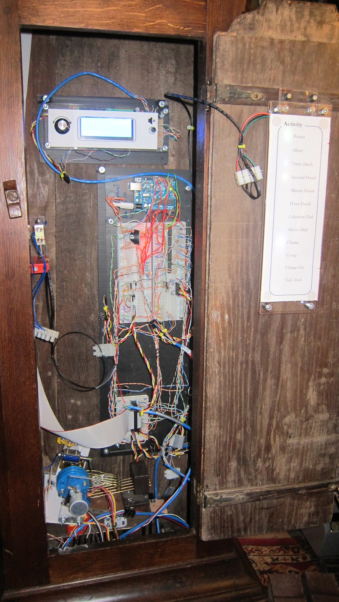
I bought this clock from long case clock specialist Paul Janes, in England. He has a fabulous collection of antique clocks. After checking out his web site, we emailed a few times to settle on a clock I liked. He was very flexible in selling me a clock without the movement. Paul took care of professionally shipping the clock to California via air freight. This isn't a trivial procedure - for the customer, it involves customs declarations, power of attorney forms and working with multiple companies in the UK and US (who, frustratingly, all like to use fax machines and photocopies!). At one point, my clock was "lost in transit" for five days. After about 8 weeks, the clock arrived via truck. It was in great shape - only the glass was broken (turbulence at 35,000 feet?).
|
 |
I started this project just after Thanksgiving in November, 2016. I finished in July, 2017. During weekdays I worked on the clock for an hour or two at night, after work. On weekends I tried to put in a couple of extra hours.
|
 |
I cleaned up the case with trusty Old English polish.
|
 |
So - can you tell there's a computer inside?
|
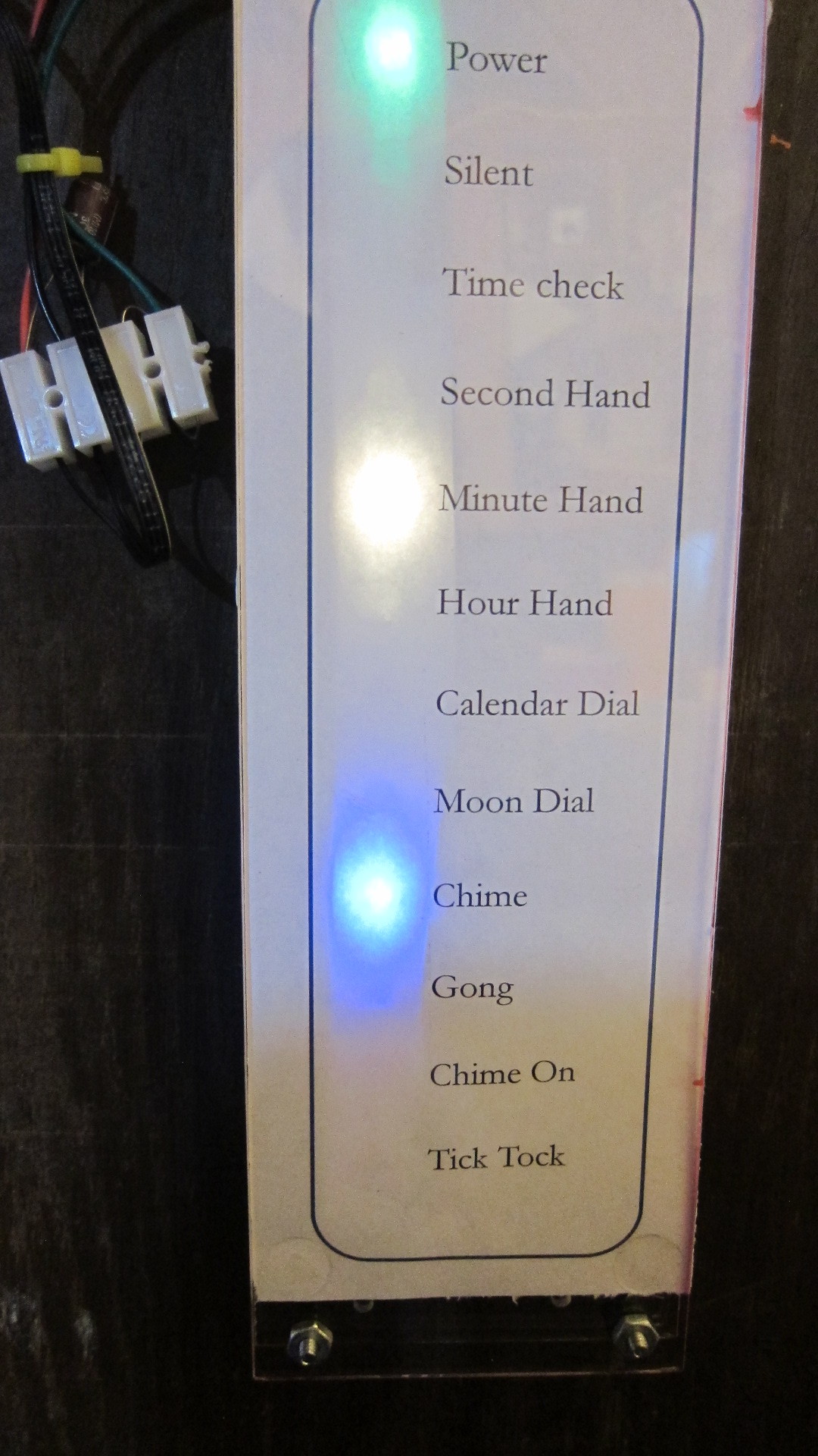 |
A close-up of the activity panel. The lights are more subtle than they appear in this photo.
|


